I received my RAK19007 base board, RAK4631 core, and RAK12501 GPS module to start a personal project of mine. Initial testing has gone great and I’m parsing the NMEA messages fine to write over serial and I decided some benchmarking was in order. Interested in testing the cold/warm/hot start claims from the product page, I tried understanding the schematics to see how to put it into standby. That’s when I realized, it does not appear we’re capable of doing so.
If I understand the schematics correctly, standby is paired with the reset so when I pull P1_02 I’m completely killing the power to the module, no? A critical reason I chose this module was to be capable of putting it into standby with decent cold and warm start times (my aim is to hold it in standby for a while and only bring it back to keep the almanac or ephemeris valid, depending on how frequent I want it to wake). My assumption appears correct in benchmarking, where my TTF averages 20 seconds with best cases being barely under the claimed <15 cold start and worst cases being well into the 30s. The chip manufacturer being used only claims <30 cold start, so why does RAK advertise better?
The module can be put in low power mode by switching of 3V3_S (through WB_IO2). The last location will still be available on next power up because the V_BCKP is always powered through 3V3.
My testing when pulling that low is that it appears to lose its RAM and takes just as long to get a fix no matter what. I will attempt to get a voltage off of V_BCKP in the process to see.
I believe you got a fast cold start. Neither your docs or manufacturer specifications document a warm start, and within 300 seconds you should have gotten a <2 second hot start (I don’t see how you would’ve had an invalid ephemeris that fast unless you were unlucky), which seems to prove what I believe is the case? I’ve also had sub-15 second cold starts every now and then.
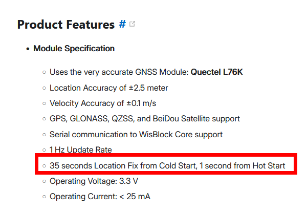
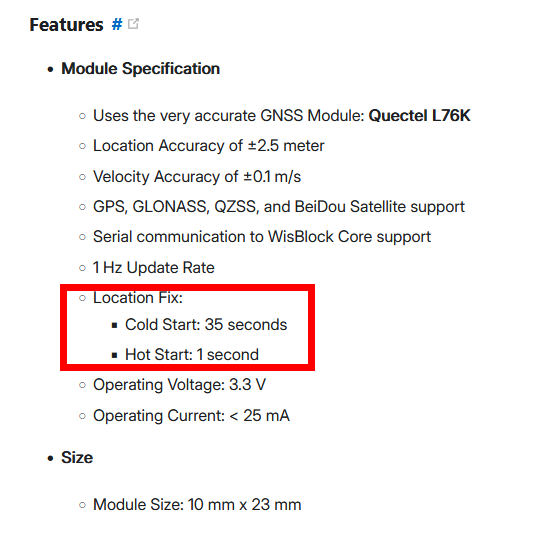
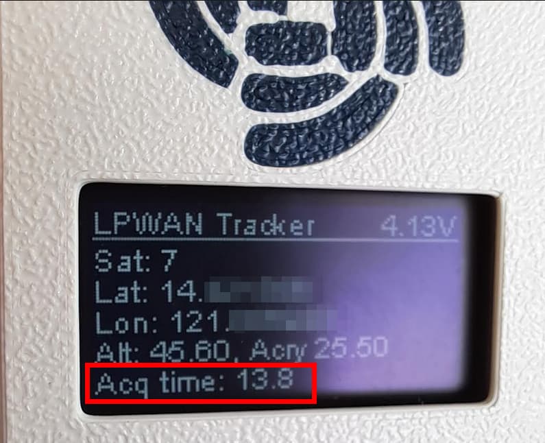
The longest I’ve ever had a fix from cold start has been 35 seconds. Continued testing shows an average of 20 seconds with best cases being 13/14. Again, all cold starts with the entire board having no power for several seconds. Neither the manufacturer nor your docs specify a warm start, and a hot start would be within 2 seconds.
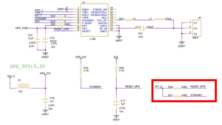
From what you have explained and what others I’ve asked seem to understand, the reset and standby pins of the L76K are junctioned and it is impossible to put the 12501 into standby as a result. If you’re saying that NC for R28 means not connected, then that means R31 is also not connected and IO2 would do nothing at all.
Either the schematics uploaded for the RAK12501 are incorrect, or as I originally asked you cannot place this chip into standby without desoldering R28. I don’t want to sound argumentative or rude, but frankly it doesn’t seem like you’re reading my posts entirely or are at least dismissing them outright such as my statement about a warm start not existing for this chip.
Curious to hear back regarding R28 and R31 as well as your testing claims. As there’s no silkscreen on a PCB this small, I cannot confirm whether one or the other is the “NC” as you claimed since they’re both labeled as such.
After checking with our Hardware R&D team I can confirm that the schematics are correct and neither R28 nor R31 are assembled.
After checking with our Software R&D team I can confirm that the device is using a warm boot when applying the sequence that I shared before.
My primary concern is still with the fact that this chip has no warm start claims either by RAK or by Queltec, the chip manufacturer. Your sequence, if pulling P1.02 (WB_IO2) is to place the chip into standby, should produce a hot start with under 2 second acquisitions.
Secondary to that is now my confusion as to how it is expected to be placed into standby. If R28 and R31 are not assembled, that would imply that IO7_2 goes straight into the reset and standby pins, or that IO7_2 does nothing and that pulling P1.02 shouldn’t do anything at all.
R28 and R31 not assembled means that the reset and standby are only connected to pull-up resistors and are not connected to IO2.
IO2 controls the main supply of the module, but the chip is still receiving 3.3V on its V_BCKP pin.
I don’t know what your code is doing, but I am having warm-boot behavior with my example code and so does our R&D team.
Okay, let’s say you’re getting a warm boot even though Queltec does not state there is one. If you’re going into standby and coming back up after only 5 minutes, you should be getting a hot start, not warm. Do you have an example where a hot start is physically possible?
Also, I simply cannot find where IO2 is connected to anything in the schematic. I’m new to reading them so it’s very possible I’m missing it. Could you show where that is?
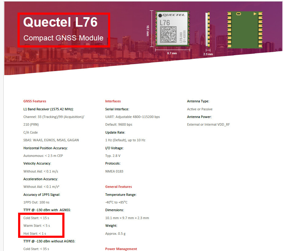
Hot start is if the module is powered up and leaves standby mode.
Warm start is if the module was powered of, but had V_BCKP supplied with 3.3V
Cold start is if the module was powered up without V_BCKP or after issuing a hardware reset
That is for the L76, not the L76K which is what the RAK12501 is. The package on my PCB is explicitly labeled “L76K” and the manufacturer documentation does not state a warm start, as well as the cold start being the same as the RAK documentation claims, so that document is not the chip in question (you’ve also highlighted with AGNSS AKA Assisted GNSS, which requires the chip being provided almanac/ephemeris data via the controller).
I’m also confused by your definition of the starts. Hot and warm should be nearly identical, that being the module remains in standby in some capacity (V_BCKP supplied). The differences lie between hot starts generally being when the module is pulled out of standby within 2 hours so it still has valid ephemeris and almanac data and the device not having moved far since. Warm starts are when the device has either moved too far for manual calculations or it has been long enough for data to expire, requiring it to acquire more data from satellites before being confident in a fix.
If your understood difference between warm and hot is true, how are we to control the standby pin in order to achieve hot start times? My end goal is going to use my own BOM and schematic, but I bought into this ecosystem hoping to explicitly test between the starts for the project I have in mind and be confident in the process. If I cannot control standby and the chip has no documented warm start behavior, then the times you’re receiving are possibly based off estimated/dead reckoning fixes.
With that said, I have narrowed my benchmarking further to produce more reliable data and can conclude that while I believe the schematic is inaccurate in its current state (P1.02/WB_IO2/IO7_2 goes nowhere if R28 and R31 are not assembled), I am receiving faster (but not hot start) fix times so long as I wait until the chip gets a quality fix with a decent number of satellites in view before pulling the power.