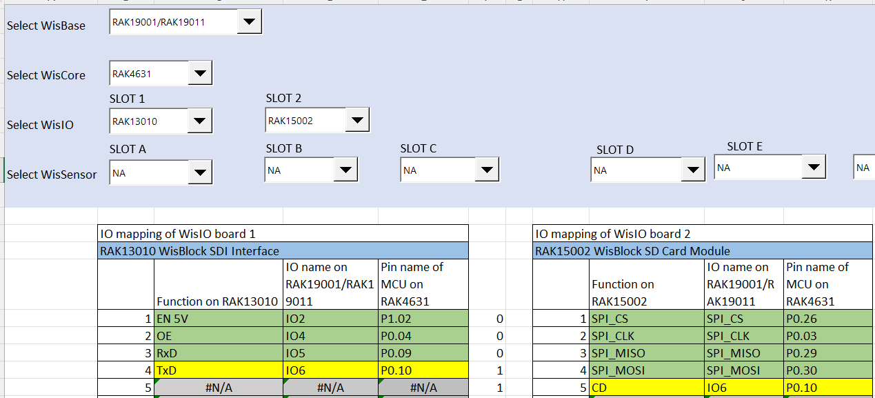
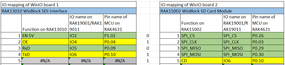
I bought the RAK19001 base board with 2 IO slots to install a RAK13010 SDI-12 module and a RAK15002 SD card module. Unfortunately, I just discovered the Pin Mapper tool and realized that IO6 is used by both modules…
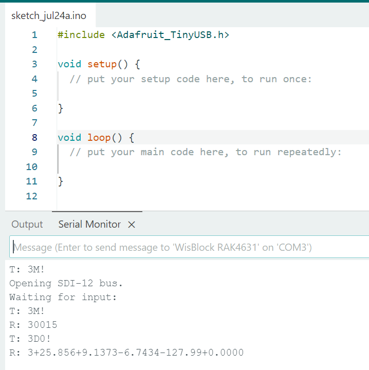
Since I connected both modules to the board, I can no longer upload any new code to the device. The current SDI-12 Data Request sketch already loaded runs correctly, but I’m unable to upload anything new: the COM port becomes unconfigurable and inaccessible.
The error :
Traceback (most recent call last):
File “nordicsemi\dfu\dfu_transport_serial.py”, line 198, in open
File “serial\serialwin32.py”, line 33, in init
File “serial\serialutil.py”, line 244, in init
File “serial\serialwin32.py”, line 80, in open
File “serial\serialwin32.py”, line 222, in _reconfigure_port
serial.serialutil.SerialException: Cannot configure port, something went wrong. Original message: OSError(22, ‘Le d�lai de temporisation de s�maphore a expir�.’, None, 121)
My first question is: how can I get out of this “locked” mode? I’ve tried the double reset procedure, but no blue LED appears and uploads still fail.
My second question is: regarding the compatibility of the RAK13010 and RAK15002, is there any way to solve the IO6 conflict—either by changing GPIO assignments in the code or physically on the board?
I am not sure what causes the “locked” mode as you describe it. But you can probably try to remove the modules and see if it the upload will push thru. However, the connection is directly going to USB peripheral of RAK4631 so there should be no conflict. What you can try as well is to put external supply instead of depending on the USB as source. You can also try to change the USB port.
For the IO6 conflict, it seems there is no work around since there are no changeable resistor on the board. There are modules that has this extra resistors but not on the SD card and SDI-12. Your option is to use an external SD card instead.
Thank you very much for your quick response.
Unfortunately, even after removing both the SDI-12 and SD modules from the board and switching USB ports, the upload still fails.
Would reflashing the bootloader help in any way?
Regarding the conflict on pin IO6, would it be possible to disregard the SD card detection pin (IO6) and leave it available for SDI-12 communication in the code? (for example, by forcing it high or disconnecting it)
Also, what do you mean exactly by an “external SD card”?
When you removed the two modules, does the RAK4631 still detected (COM port and drive) when you double click? If not, few things to check are (1) USB cable, (2) voltage of VDD if stead 3.3v or (3) if there are unusual current consumption. I wont expect more than 100mA steady consumption. I hope nothing is damage. You can try to use external tool like Jlink or RAKDAP1 to reupload the bootloader.
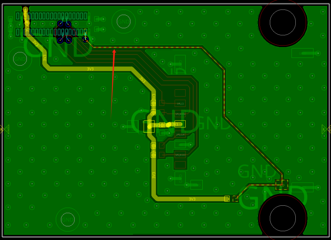
IO6 is possible if we can cut the connection to CD “Card Detect”. I do not have the pcb files to check where to cut the trace. It is not possible just forcing it low or high because IO6 is used directly by SDI-12 communication.
What I mean with external is use SD Card module and connect it via the headers.
Thank you very much for the advice and the PCB trace. I think I’ll try cutting it with a cutter or something similar and test it out.
Regarding the RAK4631, it is detected via the COM port and successfully communicates SDI-12 sensor data. When both modules are connected, it is still visible, but I’m unable to upload anything in either case.
Also, once I’ve cut the trace, do you think it will be necessary to modify, either in the code that writes files to the SD card or in the SD.h library, the condition for detecting the card (CD pin)?
If yes do you know where to do that ?
If it still goes to bootloader mode after double click on reset, use that COM port on uploading. The port sometimes change when in bootloader mode.
Chip detection is not implemented on the library. I think it is more on application use case scenario so I believe you can still use it with CD disconnected.
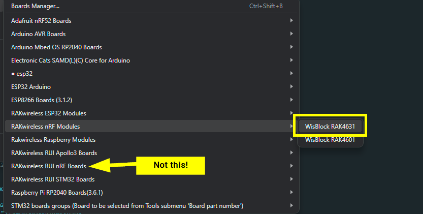
The code you have is for Arduino BSP → #include <Adafruit_TinyUSB.h>.
Can you can if you can send AT+VER=?. You can forced bootloader mode using AT+BOOT but after this command you disconnect to serial connection then try to reupload.
I think I tried with both BSP but the RUI one is very slow to compile and upload compare to the Arduino one.
The command AT+VER=? doesn’t return anything, and the AT+BOOT command does indeed disconnect the serial port, but I still can’t upload anything afterward.
It appears that RUI3 AT commands still works with the AT+BOOT but it is strange that AT+VER=? is not working. It should work either you are in bootloader mode or in application code.
Maybe it’s because the code gets stuck in the core that requests and prints SDI-12 sensor data every time the Enter key is pressed in the serial monitor.
I have cut the CD pin from the RAK15002 SD card module as you suggested, and I can now successfully write the data recorded by my SDI12 sensors onto the SD card!
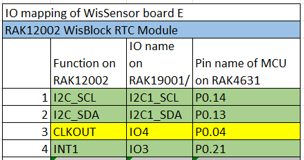
However, I have another question: I have a RAK12002 RTC module that I would like to connect to my RAK19001 board to optimize the overall system autonomy. Unfortunately, I’m still facing pin conflicts:
By connecting my RTC to sensor slot E (which is larger than my sensor size, but I don’t think this will be a problem?), the RTC’s CLKOUT output ends up on the same OE pin (IO4) used by my SDI12 module.
Would it be possible to disable this CLKOUT clock output to free up IO4 for the SDI12 module? I only need to use the RTC’s timekeeping and interrupt (INT1) functions.
This will be a challenge. I’ve looked on the datasheet and the CLKOUT has pushpull output and it has no high input impedance state that can allow you to put it together with another module. CLKOUT and OE pin cannot mix together.
For future builds of this system, would it be possible to order a custom WisBlock module where the CLKOUT pin is not connected to the WisBlock connector?
Having RAK13010 already occupied sensor slots 2,4,5 and 6. This limits you to use any other modules that uses those slots.
Custom RAK12002 is the way to do it but custom board needs to be designed to remove CLKOUT. For this request, please send email to [email protected] for the costing/quotation.