i am trying to use RAK4631, RAK13010 on RAK19007.
AT+VER=RUI_4.2.3_RAK4631
OS Windows
i use the code below to measure TDR315 and send data to gateway RAK7268CV2
when i use USB cable i see packet received in the gateway server.
when i try to use battery instead nothing is received in the gateway server.
i tried both internal and external 12V supply to the SDI12 sensor.
i saw in this forum that there was also issues with deep Sleep power. is this already been fixed?
thank you for your response
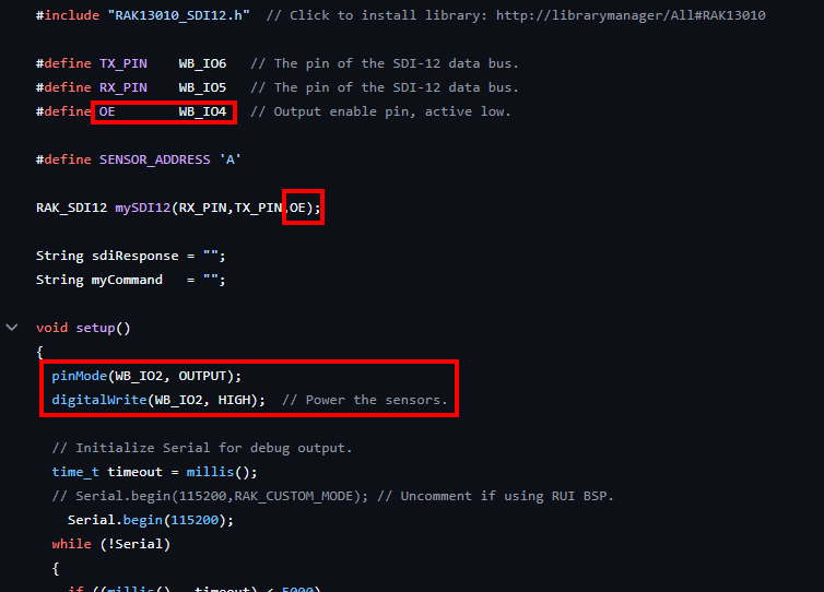
#include “RAK13010_SDI12.h”
#define TX_PIN WB_IO6
#define RX_PIN WB_IO5
#define OE WB_IO4
#define SENSOR_ADDRESS ‘A’
RAK_SDI12 mySDI12(RX_PIN, TX_PIN, OE);
// ── Reading interval ──────────────────────────────
#define SEND_INTERVAL_MS 60000 // 1 minutes
#define LORAWAN_FPORT 2
uint8_t payload[10];
bool joinDone = false;
// ────────────────────────────────────────────────
void setup() {
pinMode(WB_IO2, OUTPUT);
digitalWrite(WB_IO2, HIGH);
delay(500);
Serial.begin(115200);
delay(2000);
mySDI12.begin();
delay(500);
Serial.println(“TDR-315 + LoRaWAN | Boot”);
}
// ────────────────────────────────────────────────
void loop() {
mySDI12.clearBuffer();
// ── Step 1: M! ───────────────────────────────
String cmd = String(SENSOR_ADDRESS) + “M!”;
Serial.print("Sending: "); Serial.println(cmd);
mySDI12.sendCommand(cmd);
delay(1000);
String response = “”;
while (mySDI12.available()) {
char c = mySDI12.read();
if (c == ‘\r’ || c == ‘\n’) break;
response += c;
}
Serial.print("M! response: "); Serial.println(response);
if (response.length() < 2) {
Serial.println(“M! failed — retrying”);
delay(3000);
return;
}
int waitTime = response.substring(1, 4).toInt();
Serial.print("Sensor ready in: "); Serial.print(waitTime); Serial.println(“s”);
delay(waitTime * 1000 + 3000);
mySDI12.clearBuffer();
// ── Step 2: D0! ───────────────────────────────
String dataCmd = String(SENSOR_ADDRESS) + “D0!”;
Serial.print("Sending: "); Serial.println(dataCmd);
mySDI12.sendCommand(dataCmd);
delay(1000);
String data = “”;
while (mySDI12.available()) {
char c = mySDI12.read();
if (c == ‘\r’ || c == ‘\n’) break;
data += c;
}
Serial.print("Raw data: "); Serial.println(data);
if (data.length() < 2) {
Serial.println(“D0! failed — retrying”);
delay(3000);
return;
}
// ── Step 3: Parse 5 values ────────────────────
float values[5] = {0, 0, 0, 0, 0};
int idx = 0, pos = 1;
while (pos < (int)data.length() && idx < 5) {
int next = pos;
while (next < (int)data.length() && data[next] != ‘+’ && data[next] != ‘-’) next++;
if (next >= (int)data.length()) break;
int end = next + 1;
while (end < (int)data.length() && data[end] != ‘+’ && data[end] != ‘-’) end++;
values[idx++] = data.substring(next, end).toFloat();
pos = end;
}
float vwc = values[0];
float temp = values[1];
float ec = values[2];
float perm = values[3];
float period = values[4];
Serial.println(“──────────────────────────────────”);
Serial.print(“VWC : “); Serial.print(vwc, 3); Serial.println(” %”);
Serial.print(“Temperature : “); Serial.print(temp, 1); Serial.println(” C”);
Serial.print(“Bulk EC : “); Serial.print(ec, 1); Serial.println(” uS/cm”);
Serial.print(“Permittivity : “); Serial.print(perm, 2); Serial.println(””);
Serial.print(“Period : “); Serial.print(period, 0); Serial.println(” us”);
Serial.println(“──────────────────────────────────”);
// ── Step 4: Join ─────────────────────────────
if (!joinDone) {
Serial.println(“Joining LoRaWAN…”);
api.lorawan.join();
for (int i = 0; i < 15; i++) {
  delay(1000);
  Serial.print(".");
  if (api.lorawan.njs.get()) break;
}
Serial.println();

if (api.lorawan.njs.get()) {
  Serial.println("Joined!");
  delay(2000);
  joinDone = true;
} else {
  Serial.println("Join failed — will retry next cycle.");
}
}
// ── Step 5: Send uplink ───────────────────────
if (api.lorawan.njs.get()) {
uint16_t vwc_enc = (uint16_t)(vwc * 100);
int16_t temp_enc = (int16_t) (temp * 10);
uint16_t ec_enc = (uint16_t)(ec);
uint16_t perm_enc = (uint16_t)(perm * 100);
uint16_t period_enc = (uint16_t)(period);
payload[0] = (vwc_enc    >> 8) & 0xFF;  payload[1] = vwc_enc    & 0xFF;
payload[2] = (temp_enc   >> 8) & 0xFF;  payload[3] = temp_enc   & 0xFF;
payload[4] = (ec_enc     >> 8) & 0xFF;  payload[5] = ec_enc     & 0xFF;
payload[6] = (perm_enc   >> 8) & 0xFF;  payload[7] = perm_enc   & 0xFF;
payload[8] = (period_enc >> 8) & 0xFF;  payload[9] = period_enc & 0xFF;

// Send — ignore return value (RUI3 bug: returns false even on success)
api.lorawan.send(10, payload, LORAWAN_FPORT, false, 0);
Serial.println("Uplink transmitted.");
delay(5000);  // wait for TX_DONE
}
// ── Step 6: Sleep ─────────────────────────────
Serial.print(“Sleeping “);
Serial.print(SEND_INTERVAL_MS / 60000);
Serial.println(” min…”);
delay(100);
api.system.sleep.all(SEND_INTERVAL_MS);
joinDone = false; // rejoin after every sleep
}