RAK18032 + RAK11200 Changing samplingFrequency to 160,000 doesn't work

Hi, I have an application where I want to record and transmit amplitudes at certain ultrasound frequency as a bat detector/recorder. I bought the RAK18032 module and combined it with RAK11200. I have been playing around with the included HighRatePDMSerialPlotterFFT to try to detect 80kHz sound, but it’s not been working.

I have been testing it at a simple human-audible wavelength ~20kHz. It works up to static const int frequency = 96000 and const double samplingFrequency = 96000. If I increase those to let’s say 160k to then try to capture the 80khz sounds I want, it shifts the 20khz frequency up.

I wonder if it has anything to do with a PDM clock rate set somewhere else? Where can I set the PDM clock? Is RAK11200 suitable for this application or should I try to use something else?

/**
   @file PDMSerialPlotterFFT.ino
   @author rakwireless.com
   @brief This example reads audio data from the PDM microphones, and prints
   out the FFT transfer samples to the Serial console. The Serial Plotter built into the
   Arduino IDE can be used to plot the audio data (Tools -> Serial Plotter)
   @note  This example need use the microphones that can supports higher sampling rate.
   @version 0.1
   @date 2022-06-6
   @copyright Copyright (c) 2022
*/

#include <Arduino.h>
#include "audio.h"

int channels = 1;
// default PCM output frequency
static const int frequency = 96000;
// buffer to read samples into, each sample is 16-bits
short sampleBuffer[BUFFER_SIZE];

// Audio sample buffers used for analysis and display
int approxBuffer[BUFFER_SIZE];   // ApproxFFT sample buffer
const double samplingFrequency = 96000;     //

int print_string[500] = {0};

void onPDMdata();

void setup() {

  pinMode(WB_IO2, OUTPUT);
  digitalWrite(WB_IO2, HIGH);
  delay(500);
  pinMode(LED_GREEN, OUTPUT);
  digitalWrite(LED_GREEN, HIGH);

  // Initialize Serial for debug output
  time_t timeout = millis();
  Serial.begin(115200);
  while (!Serial)
  {
    if ((millis() - timeout) < 3000)
    {
      delay(100);
    }
    else
    {
      break;
    }
  }

  // initialize PDM with:
  // - one channel (mono mode)
  // - a 200 kHz sample rate
  // default PCM output frequency
  if (!PDM.begin(channels, frequency)) {
    Serial.println("Failed to start PDM!");
    while (1) yield();
  }

  pinMode(LED_BLUE, OUTPUT);
  digitalWrite(LED_BLUE, HIGH);
}
static uint8_t first_flag = 0;
void loop() {

  // Read data from microphone
  int sampleRead = PDM.read(sampleBuffer, sizeof(sampleBuffer));

  sampleRead = sampleRead >> 1; //each sample data with two byte
  // wait for samples to be read
  if (sampleRead > 0) {
    // Fill the buffers with the samples
    memset(approxBuffer, 0, sizeof(approxBuffer));

    for (int i = 0; i < BUFFER_SIZE; i++) {
      approxBuffer[i] = sampleBuffer[i];
      //Serial.println(approxBuffer[i]);
    }

    if (first_flag > 10)  //Discard the first 10 samples of data
    {
      Approx_FFT(approxBuffer, BUFFER_SIZE, samplingFrequency);
      //   1. in[]     : Data array, 2. N        : Number of sample (recommended sample size 2,4,8,16,32,64,128,256,512...), 3. Frequency: sampling frequency required as input (Hz)
      //      for (int j=0; j<BUFFER_SIZE; j++){
      //      Serial.println(approxBuffer[j]);
      //      }
      memset(print_string, 0, sizeof(print_string));
      memcpy(print_string, approxBuffer, sizeof(approxBuffer));

      /*
      for (int j = 0; j < 500; j++)
      {
        //Serial.println(print_string[j]);
      }
      */
      delay(5000);
    }
    else
    {
      first_flag++;
    }
    sampleRead = 0;
  }
}

Hi,

The RAK11200 is the better WisCore to use as it can run the PDM at higher rates than our Nordic based core. ( The ESP PDM Clock can reach to 16.6MHz. With the fixed decimation ratio of 64 gives a PCM clk (sampling rate) of 500kHz).

Q1: For your test: when using a sampling frequency of 160kHz is your test sound still a ~20kHz sound?
Q2: If you lower the rate down to 120 kHz do you still see the problem?

I will try to reproduce your problem as well…

I do not have the ability to generate high frequency audio (I have asked the factory to test as well), but when testing I see the following:

Sample Test Audio
Rate 1 kHz 2 kHz 8 kHz 10 kHz
160 kHz 1116 2521 10772 13740
100 kHz 1071 1978 7918 10086
96 kHz 1032 1911 7923 10074

Is this a similar magnitude of error you are seeing?

Q1. Yes. I changed both “static const int frequency” and “const double samplingFrequency” to 160k and my test sound is still ~20khz. Maybe let me try to explain… When I play a 20khz sound and both frequency and samplingFrequency is set at 100k, it gives me the correct output whereby the “dB” maxima is at 20khz. (Other note: There seems to be some sort of error or resonance also at about 35khz for some reason). However, when I set both frequency and sampling Frequency to something higher like 120k, 160k, 200k, the maxima frequency is moved up… I don’t have the exact number with me right now, but it goes up proportionally… Ie it’s 21khz at samplingFreq of 120k, 23khz at samplingFreq of 160k, etc. I tested this at various frequencies (not just 20khz but also 15khz and 10khz). There is a similar shift up. That should answer your Q2 too.

I am not sure I understand your notes here:
Sample Test Audio
Rate 1 kHz 2 kHz 8 kHz 10 kHz
160 kHz 1116 2521 10772 13740
100 kHz 1071 1978 7918 10086
96 kHz 1032 1911 7923 10074

96, 100, 160khz are sampling frequency? Can you maybe explain a little bit… Which variables are you changing for these tests… What frequency of sound did you generate?

I am trying to understand your notes here:“With the fixed decimation ratio of 64 gives a PCM clk (sampling rate) of 500kHz.”

How do I check or change the decimation ratio? Where would that be? What does this PCM clk of 500khz mean? Would that be the limiting amount I can set the frequency and samplingFrequency?

Finally, what’s the difference between the variables “frequency” and “samplingFrequency”?

Thank you for your responses.

Hi,

Thanks for the clarification - I am in discussions with our engineer about reproducing what we are seeing to determine the cause (I suspect it may be the Approx_FFT function, or the actual sample rate that is generated to the microphone not being exactly what we expect due to the clocking ratios that the PDM.begin function creates within the ESP)

Sorry that my table was a bit confusing. I tested various tones (1,2,8,10kHz) at different sampling frequencies (160,100,96kHz). I then noted the peak frequency as output by the Approx_FFT function. My results show that there is some skew happening as the sample rate rises. (My results aren’t 100% accurate due my DAC, Amp & speaker not being 100% accurate)

Frequency and samplingFrequency are used to set-up the PCM of the ESP and the FFT respectively (the code could be simplified to just use one variable)

My notes on the decimation ration and sampling rate (500kHz) are about the internal sampling within the PCM block within the ESP32 - there is nothing we can change there.

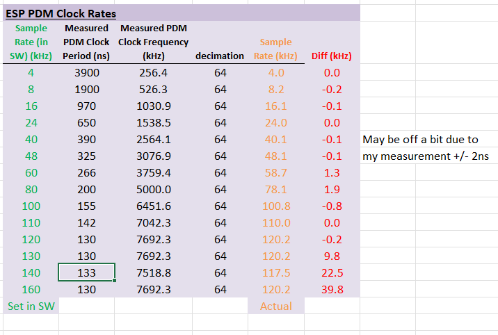
Thank you. Yes, now I understand the table you shared. That’s exactly the error I was talking about.

Want to confirm that Frequency and samplingFrequency should be set to the same values right?

I found an error with the ApproxFFT function that I corrected. I believe it was this line: “out_im[i] = out_im[i-1] + fstp;”

Just in case it’s not, I pasted my ApproxFFT below too:

//-----------------------------FFT Function----------------------------------------------//
/*
  Code to perform High speed and Accurate FFT on arduino,
  setup:

  1. in[]     : Data array,
  2. N        : Number of sample (recommended sample size 2,4,8,16,32,64,128,256,512...)
  3. Frequency: sampling frequency required as input (Hz)

  It will by default return frequency with max aplitude,
  if you need complex output or magnitudes uncomment required sections

  If sample size is not in power of 2 it will be clipped to lower side of number.
  i.e, for 150 number of samples, code will consider first 128 sample, remaining sample  will be omitted.
  For Arduino nano, FFT of more than 256 sample not possible due to mamory limitation
  Code by ABHILASH
  Contact: [email protected]
  Documentation & details: https://www.instructables.com/member/abhilash_patel/instructables/

  Update(06/05/21): Correction made for support on Arduino Due
*/

//---------------------------------lookup data------------------------------------//
byte isin_data[128] =
{ 0,  1,   3,   4,   5,   6,   8,   9,   10,  11,  13,  14,  15,  17,  18,  19,  20,
  22,  23,  24,  26,  27,  28,  29,  31,  32,  33,  35,  36,  37,  39,  40,  41,  42,
  44,  45,  46,  48,  49,  50,  52,  53,  54,  56,  57,  59,  60,  61,  63,  64,  65,
  67,  68,  70,  71,  72,  74,  75,  77,  78,  80,  81,  82,  84,  85,  87,  88,  90,
  91,  93,  94,  96,  97,  99,  100, 102, 104, 105, 107, 108, 110, 112, 113, 115, 117,
  118, 120, 122, 124, 125, 127, 129, 131, 133, 134, 136, 138, 140, 142, 144, 146, 148,
  150, 152, 155, 157, 159, 161, 164, 166, 169, 171, 174, 176, 179, 182, 185, 188, 191,
  195, 198, 202, 206, 210, 215, 221, 227, 236
};
unsigned int Pow2[14] = {1, 2, 4, 8, 16, 32, 64, 128, 256, 512, 1024, 2048, 4096};
byte RSSdata[20] = {7, 6, 6, 5, 5, 5, 4, 4, 4, 4, 3, 3, 3, 3, 3, 3, 3, 2, 2, 2};
//---------------------------------------------------------------------------------//

float Approx_FFT(int in[], unsigned int N, float Frequency)
{
  int a, c1, f, o = 0, x, data_max, data_min = 0;
  long data_avg, data_mag, temp11;
  byte scale, check = 0;

  data_max = 0;
  data_avg = 0;
  data_min = 0;

  for (int i = 0; i < 12; i++)          //calculating the levels
  {
    if (Pow2[i] <= N) {
      o = i;
    }
  }
  a = Pow2[o];
  int out_r[a];   //real part of transform
  int out_im[a];  //imaginory part of transform

  for (int i = 0; i < a; i++)         //getting min max and average for scalling
  { out_r[i] = 0; out_im[i] = 0;
    data_avg = data_avg + in[i];
    if (in[i] > data_max) {
      data_max = in[i];
    }
    if (in[i] < data_min) {
      data_min = in[i];
    }
  }

  data_avg = data_avg >> o;
  scale = 0;
  data_mag = data_max - data_min;
  temp11 = data_mag;

  //scalling data  from +512 to -512

  if (data_mag > 1024)
  { while (temp11 > 1024)
    { temp11 = temp11 >> 1;
      scale = scale + 1;
    }
  }

  if (data_mag < 1024)
  { while (temp11 < 1024)
    { temp11 = temp11 << 1;
      scale = scale + 1;
    }
  }


  if (data_mag > 1024)
  {
    for (int i = 0; i < a; i++)
    { in[i] = in[i] - data_avg;
      in[i] = in[i] >> scale;
    }
    scale = 128 - scale;
  }

  if (data_mag < 1024)
  { scale = scale - 1;
    for (int i = 0; i < a; i++)
    {
      in[i] = in[i] - data_avg;
      in[i] = in[i] << scale;
    }

    scale = 128 + scale;
  }


  x = 0;
  for (int b = 0; b < o; b++)              // bit reversal order stored in im_out array
  {
    c1 = Pow2[b];
    f = Pow2[o] / (c1 + c1);
    for (int j = 0; j < c1; j++)
    {
      x = x + 1;
      out_im[x] = out_im[j] + f;
    }
  }

  for (int i = 0; i < a; i++)     // update input array as per bit reverse order
  {
    out_r[i] = in[out_im[i]];
    out_im[i] = 0;
  }


  int i10, i11, n1, tr, ti;
  float e;
  int c, temp4;
  for (int i = 0; i < o; i++)                             //fft
  {
    i10 = Pow2[i];            // overall values of sine/cosine
    i11 = Pow2[o] / Pow2[i + 1]; // loop with similar sine cosine
    e = 1024 / Pow2[i + 1]; //1024 is equivalent to 360 deg
    e = 0 - e;
    n1 = 0;

    for (int j = 0; j < i10; j++)
    {
      c = e * j; //c is angle as where 1024 unit is 360 deg
      while (c < 0) {
        c = c + 1024;
      }
      while (c > 1024) {
        c = c - 1024;
      }

      n1 = j;

      for (int k = 0; k < i11; k++)
      {
        temp4 = i10 + n1;
        if (c == 0)   {
          tr = out_r[temp4];
          ti = out_im[temp4];
        }
        else if (c == 256) {
          tr = -out_im[temp4];
          ti = out_r[temp4];
        }
        else if (c == 512) {
          tr = -out_r[temp4];
          ti = -out_im[temp4];
        }
        else if (c == 768) {
          tr = out_im[temp4];
          ti = -out_r[temp4];
        }
        else if (c == 1024) {
          tr = out_r[temp4];
          ti = out_im[temp4];
        }
        else {
          tr = fast_cosine(out_r[temp4], c) - fast_sine(out_im[temp4], c);      //the fast sine/cosine function gives direct (approx) output for A*sinx
          ti = fast_sine(out_r[temp4], c) + fast_cosine(out_im[temp4], c);
        }

        out_r[n1 + i10] = out_r[n1] - tr;
        out_r[n1] = out_r[n1] + tr;
        if (out_r[n1] > 15000 || out_r[n1] < -15000) {
          check = 1; //check for int size, it can handle only +31000 to -31000,
        }

        out_im[n1 + i10] = out_im[n1] - ti;
        out_im[n1] = out_im[n1] + ti;
        if (out_im[n1] > 15000 || out_im[n1] < -15000) {
          check = 1;
        }

        n1 = n1 + i10 + i10;
      }
    }

    if (check == 1) {                                         // scalling the matrics if value higher than 15000 to prevent varible from overflowing
      for (int i = 0; i < a; i++)
      {
        out_r[i] = out_r[i] >> 1;
        out_im[i] = out_im[i] >> 1;
      }
      check = 0;
      scale = scale - 1;             // tracking overall scalling of input data
    }
  }

  if (scale > 128)
  { scale = scale - 128;
    for (int i = 0; i < a; i++)
    { out_r[i] = out_r[i] >> scale;
      out_im[i] = out_im[i] >> scale;
    }
    scale = 0;
  }                                                   // revers all scalling we done till here,
  else {
    scale = 128 - scale; // in case of nnumber getting higher than 32000, we will represent in as multiple of 2^scale
  }

    /*
    for(int i=0;i<a;i++)
    {
    Serial.print(out_r[i]);Serial.print("\t");                    // un comment to print RAW o/p
    Serial.print(out_im[i]);
    Serial.print("i");Serial.print("\t");
    Serial.print("*2^");Serial.println(scale);
    }
    */

  //---> here onward out_r contains amplitude and our_in conntains frequency (Hz)
  int fout, fm, fstp;
  float fstep;
  fstep = Frequency / N;
  fstp = fstep;
  fout = 0; fm = 0;

  for (unsigned int i = 1; i < Pow2[o - 1]; i++)      // getting amplitude from compex number
  {
    out_r[i] = fastRSS(out_r[i], out_im[i]);
    // Approx RSS function used to calculated magnitude quickly
    out_im[i] = out_im[i-1] + fstp;
    if (fout < out_r[i]) {
      fm = i;
      fout = out_r[i];
    }

    // un comment to print Amplitudes (1st value (offset) is not printed)
    Serial.print(i  );
    Serial.print("\t"); 
    Serial.print(out_im[i]);
    Serial.print("\t");   
    Serial.print(out_r[i]);
    Serial.print("\t");   
    Serial.print("*2^");Serial.println(scale);
    in[i - 1] = out_r[i];
  
  }


  float fa, fb, fc;
  fa = out_r[fm - 1];
  fb = out_r[fm];
  fc = out_r[fm + 1];
  fstep = (fa * (fm - 1) + fb * fm + fc * (fm + 1)) / (fa + fb + fc);

  return (fstep * Frequency / N);
}

//---------------------------------fast sine/cosine---------------------------------------//

int fast_sine(int Amp, int th)
{
  int temp3, m1, m2;
  byte temp1, temp2, test, quad, accuracy;
  accuracy = 7;  // set it value from 1 to 7, where 7 being most accurate but slowest
  // accuracy value of 5 recommended for typical applicaiton
  while (th > 1024) {
    th = th - 1024; // here 1024 = 2*pi or 360 deg
  }
  while (th < 0) {
    th = th + 1024;
  }
  quad = th >> 8;

  if (quad == 1) {
    th = 512 - th;
  }
  else if (quad == 2) {
    th = th - 512;
  }
  else if (quad == 3) {
    th = 1024 - th;
  }

  temp1 = 0;
  temp2 = 128;    //2 multiple
  m1 = 0;
  m2 = Amp;

  temp3 = (m1 + m2) >> 1;
  Amp = temp3;
  for (int i = 0; i < accuracy; i++)
  { test = (temp1 + temp2) >> 1;
    temp3 = temp3 >> 1;
    if (th > isin_data[test]) {
      temp1 = test;
      Amp = Amp + temp3;
      m1 = Amp;
    }
    else if (th < isin_data[test]) {
      temp2 = test;
      Amp = Amp - temp3;
      m2 = Amp;
    }
  }

  if (quad == 2) {
    Amp = 0 - Amp;
  }
  else if (quad == 3) {
    Amp = 0 - Amp;
  }
  return (Amp);
}

int fast_cosine(int Amp, int th)
{
  th = 256 - th; //cos th = sin (90-th) formula
  return (fast_sine(Amp, th));
}

//--------------------------------------------------------------------------------//


//--------------------------------Fast RSS----------------------------------------//
int fastRSS(int a, int b)
{ if (a == 0 && b == 0) {
    return (0);
  }
  int min, max, temp1, temp2;
  byte clevel;
  if (a < 0) {
    a = -a;
  }
  if (b < 0) {
    b = -b;
  }
  clevel = 0;
  if (a > b) {
    max = a;
    min = b;
  } else {
    max = b;
    min = a;
  }

  if (max > (min + min + min))
  {
    return max;
  }
  else
  {
    temp1 = min >> 3; if (temp1 == 0) {
      temp1 = 1;
    }
    temp2 = min;
    while (temp2 < max) {
      temp2 = temp2 + temp1;
      clevel = clevel + 1;
    }
    temp2 = RSSdata[clevel]; temp1 = temp1 >> 1;
    for (int i = 0; i < temp2; i++) {
      max = max + temp1;
    }
    return (max);
  }
}
//--------------------------------------------------------------------------------//

Yes, Frequency and samplingFrequency should be set to the same values.

I’m not sure about the change you’ve noted - it depends on which version of the original code (He has two versions posted at https://www.instructables.com/ApproxFFT-Fastest-FFT-Function-for-Arduino/ and we’ve used V2). The line you’ve noted is different between the two versions… Did changing this line fix the problem (I’m guessing not).

It fixed a problem, not this problem I mentioned.

Tom,
I wanted to let you know we are still looking into this - it does seem to be a clocking issue.
What problem did your change fix for you?

By any chance do you have one of our RAK4630 WisCores?

I need to investigate the results above as there is an unexpected problem above 120kHz it would seem.

Thank you for the update. I don’t have RAK4630 unfortunately.

I don’t remember the default output of the code, but I wanted to use the FFT to output the amplitude at each khz. I had to make the change so it outputs correctly.

Tom,

I have been able to get a higher PDM clock rate by changing the following file:

packages\rakwireless\hardware\esp32\2.0.3\libraries\PDM\src\PDM.cpp

Change .use_apll from true to false. This changes the clock source for the I2S/PDM peripheral.

With this I am able to generate a PDM clock up to 10Mhz (~155kHz sample rate)
image

I am still looking into if we can generate a higher clock rate, but am not sure as the ESP32 technical manual isn’t clear on this aspect. I have reached out to Espressif for more information.