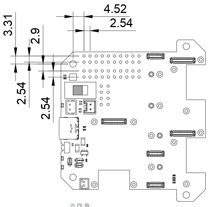
RAK19001 dual IO slot board.
I’m making a breakout board for the 19001, like I have previously for the 19007. Think of it as the opposite of a hat.
The mechanical drawing on the datasheet page of the 19001 shows the locations of everything but the J10/J15 header and the J11/J12 headers. Is this available on any other mechanical drawing? I know they are going to be 2.54mm spacing within each connector, but the spacing between connectors and their location wrt to some other referenced feature is missing.