Did the pinout of the RAK19003 change going from Rev B to Rev E? I understand the internal power management changed going from B to E. That’s fine.
I have the RAK19003 Rev B schematic from the RAK website. It shows BTB40 Pin 33/34 connected to TXD1/RXD1 and J7 TXD1/RXD1 on pin 2/1 respectively. Also J4 and J5 expose TXD1 and RXD1. The silk screen on the Rev E board J7 shows TX0/RX0. That’s fine if it’s just a naming change from schematic to PWB.
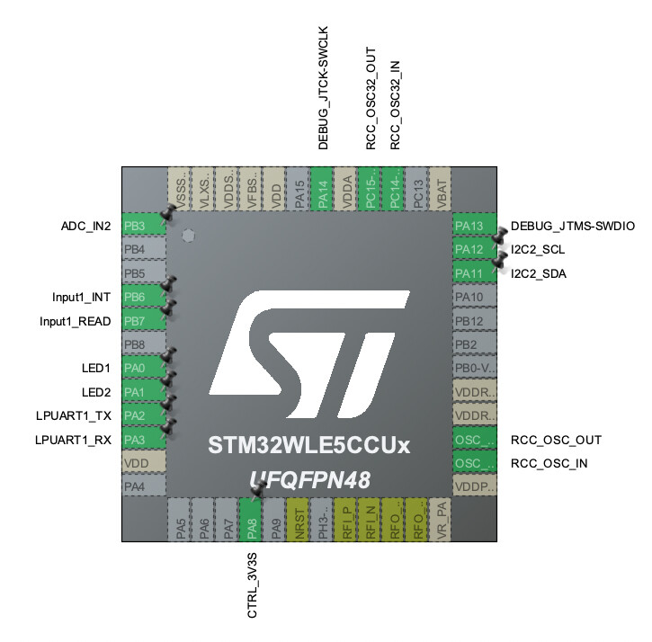
The issue I’m having is that I’m trying to pass PB6/PB7 as IO pins from the RAK3172/3372 module out to J7 TX0/RX0. I’m not seeing any continuity when I probe this path. PB6 and PB7 are on pin 4 and 5 of the RAK3172 (UART1/UART2). I’m using STM32CubeMX to redefine PB6 and PB7 to GPIO.
It looks to me like something changed going from the RAK19003 Rev B board to Rev E. This did work at one time Would sure appreciate some guidance.
The documentation must be updated with this information. This is a breaking change with real impact on projects.
The datasheet still reflects the version where the TX1 and RX1 are present in J7 header.
I noticed the changes on the silkscreen indicating the pins, but I simply followed your datasheet, which made me spend three days debugging until I realized the pins have changed. I bought this board expecting to have access to TX1 and RX1 in this header, now I need to figure out what I’m going to do…
So it’s mean that’s not anymore possible to use those Pin (Tx1/Rx1) as general IO pin as Rx0/Tx0 are used for firmware update and AT command of the module via UART2 (RAK3372 CPU board) ?!?!
And on new design (Rev E.), there’s not anymore 3v3 and 3v3_S exposed as testing pad - soooo bad !
It’s mean that we “cannot use” this board without adding an IO board on slot C/D…
Indeed, on previous design we used for our product 2 external IO pin & 3v3_S to have external sensors connected to that board and all was working fine… now : impossible

 Would sure appreciate some guidance.