
Hi everyone, I have assembled a 19007 with RAK4631, and added a RAK19002 boost converter. This powers a rain sensor. Have the device working nicely, power consumption is very little, and I installed the RAK solar panel to keep battery charged.
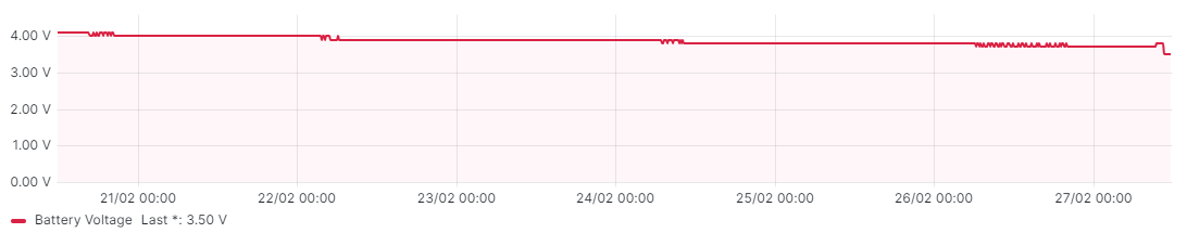
Have had in direct sunlight for over a week, and the power (via 18650 battery), has slowly crept down from 4.1v to 3.8. No upward recording of voltage at all. I then removed the boost converter (and hence the rain sensor), no change at all. Tried a different solar panel (checked it also, was providing 6v), no luck. Tried a different battery, still not increasing in charge.
I’m aware that it’s a completely separate charging circuit, any ideas of something else I could check? I’m sort of at the stage where I assume the 19007 is faulty…
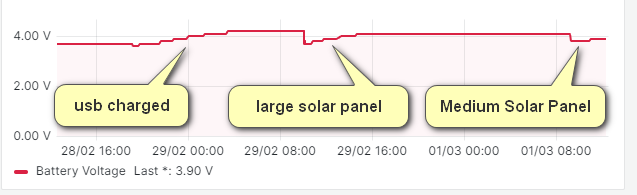
Here’s a screenshot of the voltage over the last 7 days.
EDIT: Forgot to add, I am getting a solid red led indicating charging.
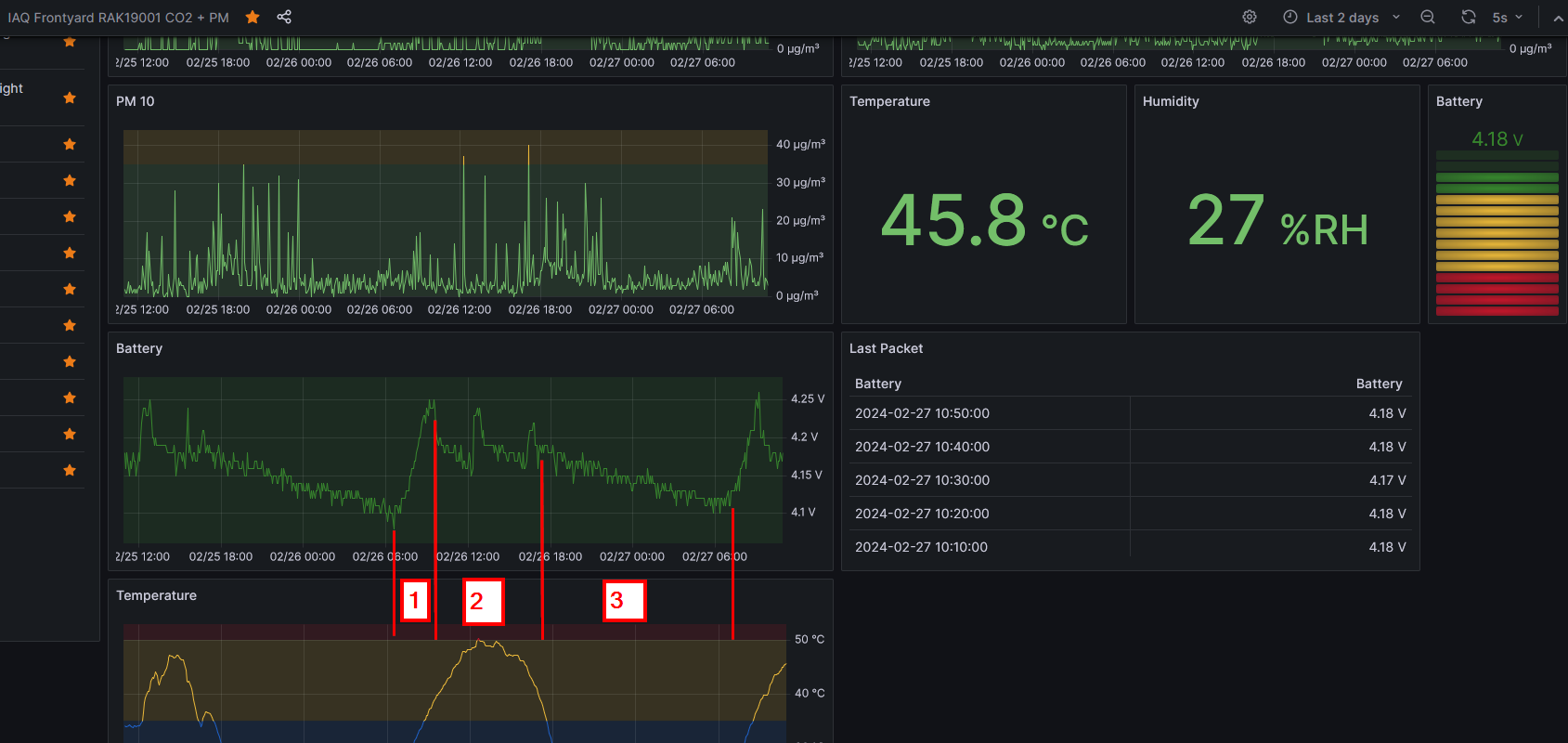
This is strange indeed. I am running multiple systems with RAK19003, RAK19007 and RAK19001 base boards in my frontyard without problems.
On my most power hungry device (CO2 sensor + Particulate Matter sensor + T&H + VOC sensor) I can see the expected behaviour:
(1) recharge in the morning when the sun comes up
(2) trickle charging during the day
(3) discharging over night
Do you have another RAK19007 for comparison?
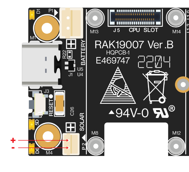
I guess you checked the polarity on the solar panel connector?
Hi @beegee, thanks for following up, yeah it’s really weird, I have plenty of devices out in the wild charging with no problems too. Devices that would chew more power than this I would think (Weather stations, ultrasonic sensors).
I have checked polarity with multimeter, it’s all good. I would assume I wouldn’t get the charging led if it were reversed?
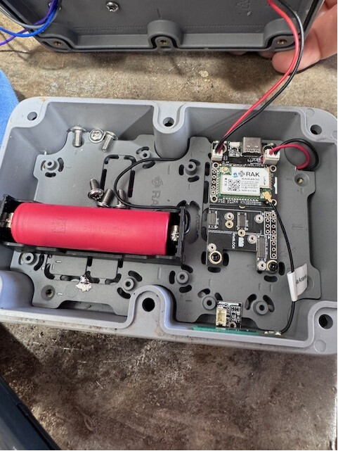
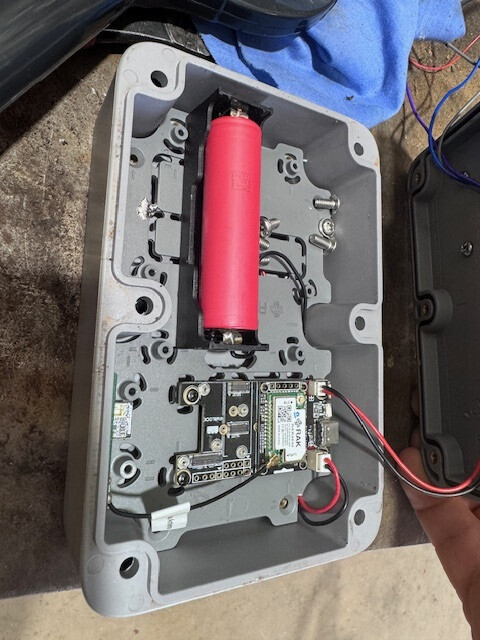
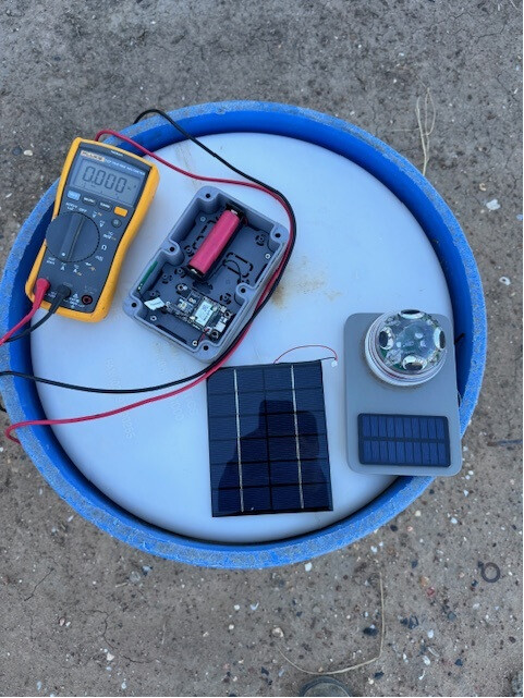
I have replaced the 19007, and will give it the rest of the afternoon to see what happens. It’s in direct sunlight with no sensor attached. After 1 1/2 hours the voltage hasn’t moved. Not looking good. Is it possible I’m simply not letting it get low enough to pump more into it? I would have though this unlikely as the panel is outputting 6v max. Here are some photos…
The charger has multiple modes and switches between them automatically. But at 3.8V battery voltage it should definitely start charging.
Flashback from another customer problem. Can you check the solar panel connector on the Base Board.
I had two cases (manufacturing failures)
(1) a pin was missing
(2) bad soldering of the connector pins
Ok, I’ll check that out, but again, I would assume with a solid red light indicating charging that the pins would be ok. I’ll put a multimeter on the solders when I get back to the device. Thanks @beegee!
I’m completely stumped, here is a screenshot of the voltage on the back of the solar input pins…all seems ok…not that the voltage is huge, but there was a bit of cloud cover whilst taking the reading.
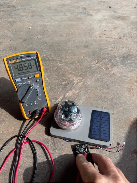
But the voltage should be ok for charging, which shows with the red LED on as well.
So we have
- looks like ok solar panel
- looks like ok solar panel connector
- looks like ok charger circuit
- looks like ok battery
- changed RAK19007
- changed battery
But it is still not charging.
I am lost, no idea what’s wrong here.
Ok, I have an update.
I put the board on usb charging to double check the board charging, the battery charged pretty quickly. No problems.
Next I tried a bigger solar panel (136110), again the battery charged quickly. Getting somewhere!
I am currently testing an in between size (11069), and it looks like it might do the job.
Question is, why isn’t the smaller RAK panel doing the job? The datasheet indicated it’s current at nominal power is 90ma (best I could get in direct sunlight was around 60ma). Is that enough that it should charge the battery with nothing on the board? I would have thought so.
As per the datasheet for the 19007…
Current Consumption
The RAK19007 is designed for low-power IoT products, and the power supply uses a high-efficiency low grounding current regulator. When there is no module on RAK19007, the leakage current is lower than 2 µA. With WisBlock Core and WisBlock Sensor on it, the sleep current is lower than 10 µA. When a LoRa module is transmitting, the current may reach 130 mA.
So still a bit stumped. Thoughts? Could there be too small a current on the smaller board to get the charging activated?
Would it be worth trying a different board just to charge the battery? (not my preferred option, defeats the purpose of having it on the wisblock).
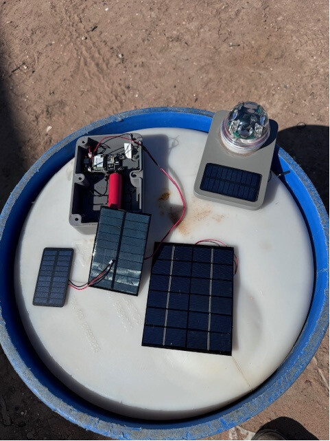
I’m having the same issue with the smaller solar panel… I tried connecting two, to see if that would help and still no luck.
I’ll keep you posted if so figure anything out!
The smaller solar panel is working perfectly for me with a low power firmware (~25uA sleep current) and a 3200mAh Li-Ion battery.
I understand you are all running the Meshtastic firmware?
I am not using that firmware in real use cases, but measuring the power consumption, I cannot see it going below 6mA. My assumption is that it cannot be lower because the LoRa transceiver is in RX mode all the time and the 6mA would be normal for that case.
Thanks @beegee, think I have worked it all out, it’s simply a power budget issue. That particular sensor pulls constant power, so both the boost module and sensor will be consuming power in addition to the 19007 itself (no deep sleep). Upon testing, with only the boost connected, the unit was consuming approx 7ma. When the sensor was connected, this increased to 14ma. I suppose the smaller panel simply can’t keep up with this.
The docs on the sensor indicate it only consumes 110 μA nominal. (No outputs on, dry not raining)
2-4 mA when raining. I would have thought this would be ok.
I think my only workaround at this stage is find the largest solar panel that will fit on the largest unifi enclosure, and hope it keeps it charged. If I can find one slightly smaller than the largest of the ones in the previous post, I would think it should be enough.
Unless I’m overlooking some functionality that might assist with the power consumption (deep sleep whilst keeping the boost module operational for example?). Your thoughts regarding this would be appreciated.
Does the boost (whatever that does) have to be powered all time? Wondering that the datasheet says 110uA nominal but you measure 7mA consumption. Maybe there is a setting for the boost to lower the consumption or go into low power mode.
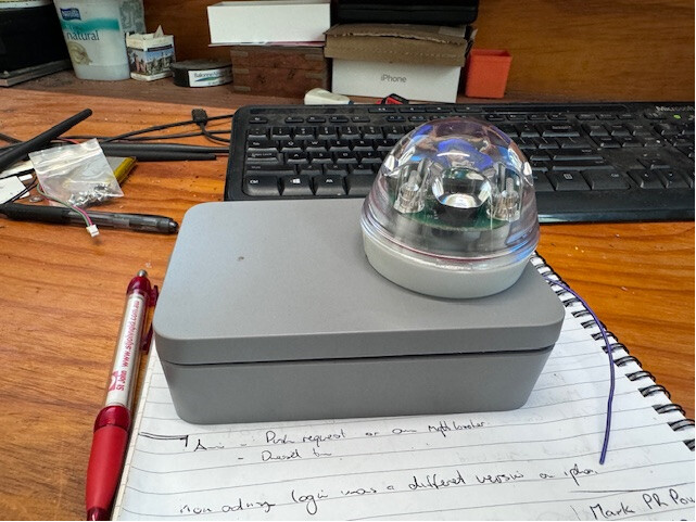
Yeah, it needs to be powered all the time. The boost I’m referring to is the RAK19002. It can be powered by 3.3v, but the instructions indicate that unless it’s a stable supply, it could induce false indications or affect accuracy.
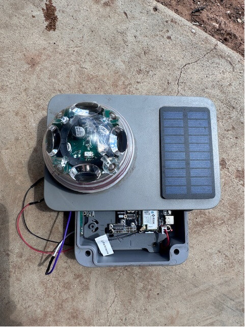
Here is the device I’m playing with…can’t find any reference to low power mode.
And the Instructions
I’ll do more testing, thanks for the assistance so far.
Another follow up, I contacted support regarding the high consumption reading, their response…
“Based on the phenomenon, I think it may be caused by the leakage of electricity from the IO port to the control board. Maybe you can deinit the IO port. Then set it to a floating input and check the power consumption again.”
So two questions from here.
- I assume they are referring to the line in the code where I call the GPIO high? If that’s the case, what would I change?
** pinMode(WB_IO2, OUTPUT);*
- digitalWrite(WB_IO2, HIGH);**
- I’m assuming I’m ok to use slot B on the 19007, there is a note under the docs stating…" * The slot B is not recommended because the IO2 pin is used to control power supply 3V3_S on WisBase RAK5005-O." I’m hoping it’s all good for the newer board?
General explanation:
WisBlock Base Boards (all of them) have a feature to power down modules in the Sensor Slots and IO Slots.
Not all WisBlock sensor and IO modules support that feature. You have to check for each module if it is powered by 3V3 or by 3V3_S. If it is 3V3_S, its supply can be shut down.
Some background for the comment about Slot B (and Slot A) regarding IO2:
The supply 3V3_S is controlled by WB_IO2, this is not a perfect solution, but WisBlock simply doesn’t have enough GPIO’s available. WB_IO2 is as well used as GPIO in Slot A and Slot B.
If a module in Slot A or Slot B is having an output signal, e.g. an interrupt output, on IO2, this is causing a problem when you control the power supply 3V3_S through IO2.
Conclusion:
If you need to control 3V3_S with WB_IO2, you can use only modules that do not use IO2 as an output in Slot A or Slot B.
If you do not control 3V3_S AND have no IO modules that use 3V3_S, you can set IO2 as input and use any module in Slot A and Slot B

Confused?

I understand, some parts of WisBlock system are not easy to understand.