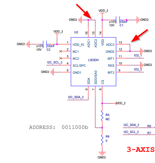
I believe this indicates that the pull-up resister is not present. Can somebody confirm that this is the case?
I’ve also been trying to do interupts (two, with a different threshold). I’ve noticed that it doesn’t seem to always work if i just reset the device (using software after upload of new firmware). If i disconnect and connect, it seems to be better. Has anybody seen this as well? Is there something i’m doing wrong?
My ‘test’ code is here. It would be great if somebody could have a look.
Yes, the pull-up resistor is not present and we found that without the external resistor the chip has a higher current consumption.
Adding this register settings help to reduce the consumption to the same level as if the resistor is present.
I have not experienced problems with the RAK1904’s functionality after uploading a new code so far. But I never tried to use both interrupts at the same time.
Thanks for confirming that the pull-up is not there.
The 2 interups seem to work fine. I’ll do some more testing and see if i can get it to work better. There’s quite a lot of documentation and it’s not super clear to me.
I also want to point out that there’s two docs. The datasheet and an application note. That application note has a lot more info…
I’m really having difficulty getting two interupts to work.
It’s not that they don’t work, they seem to not be working like i want to…
So - i’m trying to get a simple ‘it moves’ interrupt and then a ‘it fell or was moved very quickly’ interrupt.
I might not be understanding it all, so is that possible?
It seems my issues are mainly resolved when a higher ORD is selected. My aim is to get a very low power consumption while still detecting movement and erratic movement. On the ORD0 with Low Power that doesn’t seem possible.
Just an update (and question) from my side:
My code works a lot better with a higher ORD/Hz. This makes sense as the interrupt is also registered like so. The document isn’t great on this, but i guess it’s implied.
I also noticed that when the ORD is higher that the interrupt code fires and i think there’s something wrong there. I have two interrupt methods for it and i bind it to WP_05 and WP_06 with attachInterrupt. It looks like both interrupts fire at the same time and the code doesn’t handle it.
When i don’t use these interrupts but just /read/ the INTx_SRC registers then the bits there are set correctly. For my use case this is fine.
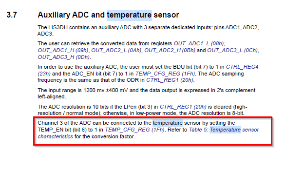
I’m also trying to read temperature, but i’m not clear if this requires a temperature sensor on ADC3, or if the temperature sensor would be built in…?! I get 0’s out of reading ADC3…
The datasheet of the LIS3DH says Embedded temperature sensor but it looks like it has to be connected by register settings to the channel 3 of the ADC.
With our layout, that could mean the temperature sensor cannot be used.