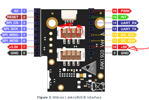
Hello, I’ve been trying for some weeks now to interface some grove sensors with the RAK1920, with low level of success, the 0.5mm resistors (according to the documentation) than need to be de solder and re solder in order to be able to work with the communication protocols different to I2C make it pretty much impossible.
I also have a problem and questions about the possible 5V output from the boost integrated in the module RAK1920, this is the setup code I use to get a 5V output(I need it for this sensor Sensor_link among others) :
Is there any other step that I need to do in order to get 5V output ?
Is it possible to have that 5V output in the grove connector interface?
(I also tried soldering a 0 ohm resistor in the R1 in another RAK1920 module even with the resistor it did not perform as expected)
I Tried this wiring to get the 5V I need to power the sensor that consumes no more than 80mA, and according with the docs the RAK1920 is able to provide up to 800mA, but as soon as I hook the sensor to the 5V output from the module the voltage drops to 2.1V.
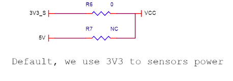
If you want to make the VCC in grove connectors to be 5V level, you dont need to short R1 since the boost is already controlled by the IO pin of WisBlock Core.
What you need is to remove R6 then short R7.
The drop across 5V can attribute to various possible reasons (few I can think off):
Is the sensor really getting only 80mA? Have you tested it externally?
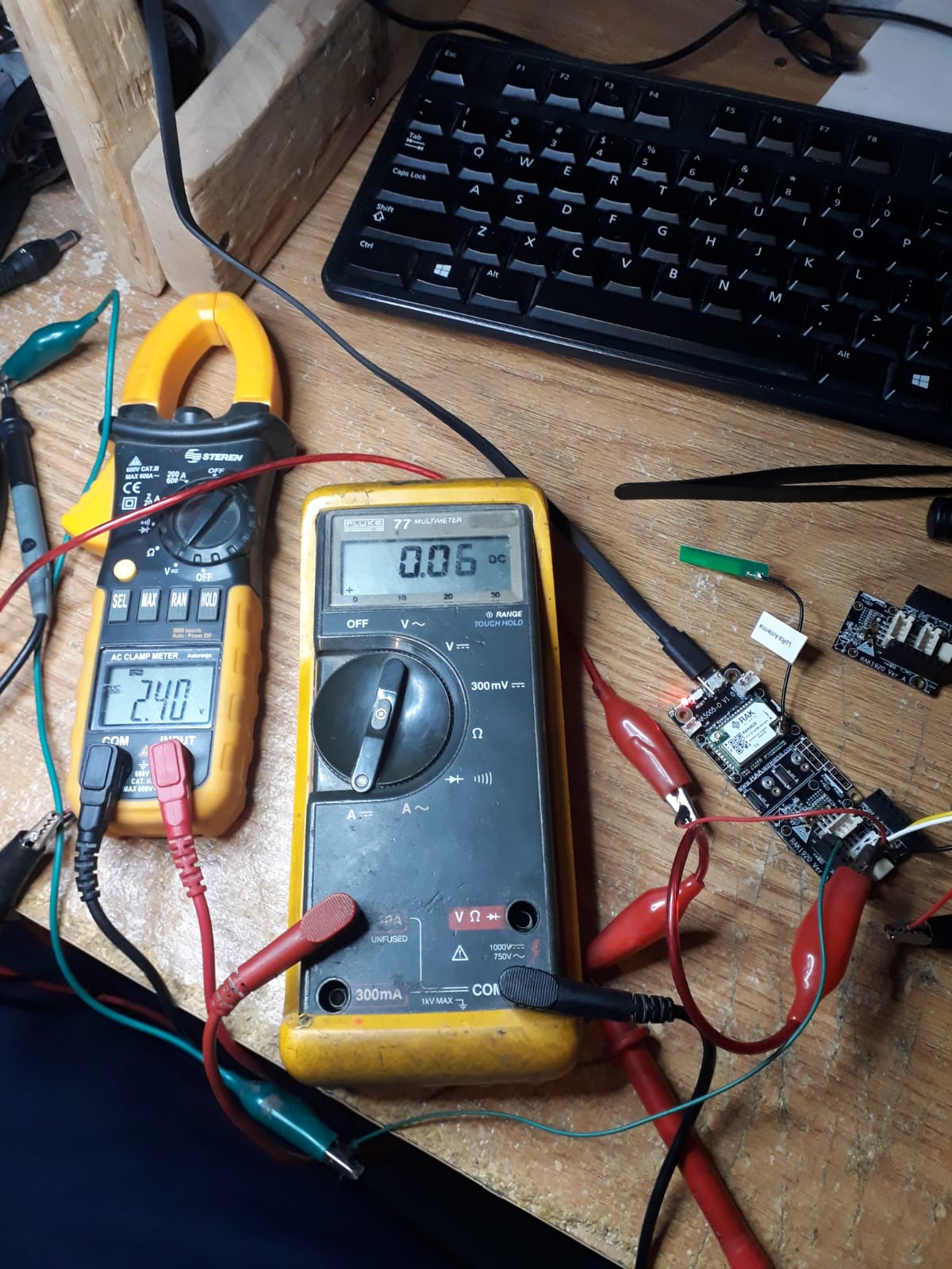
The remove R6 then short R7 definitely did work, however the boost converter in the RAK1920 is not able to hold 5V when a load of 50 - 90mA is applied to it, I attach the picture as proof, you can also contact me by mail, I can send you a video and many more pictures.
According to the documentation the Boost should be able to source up to 800mA, we tested at least 4 modules and all show the same result.
1. Is the sensor really getting only 80mA? Have you tested it externally? Yes to both, it does reach a peak of 90mA at the start then goes into steady state at 60-70mA, we did tested externally with different 5V power sources the current does not exceed 90mA
2. Are the connectors in proper arrangement? Yes they are wired the right way, is a simple 4 wire grove connector where black is GND, red is 5V, the other two wires are communication.
After all the test with the 80mA sensors, we also tested a couple of loads, a 330ohm resistor, and a 22ohm resistor, the results:
The 3.3V line will hold the voltage just fine with any of those loads.
The 5V line will hold with the 330ohm 15mA load just fine, but it will fail big time with the 22ohm 227mA load, would even make this loud buzzing sound when that load was applied, and the voltage will drop to 1.8V.
Did you guys test the module with 800mA theoretical load is able to take?
My colleagues checked it and confirmed that the guaranteed output current of the onboard boost converter is only up to 50mA. I will correct the datasheet.
It seems you need to use an external 5V power-source for your sensor.