RAK2247 Reset Active High

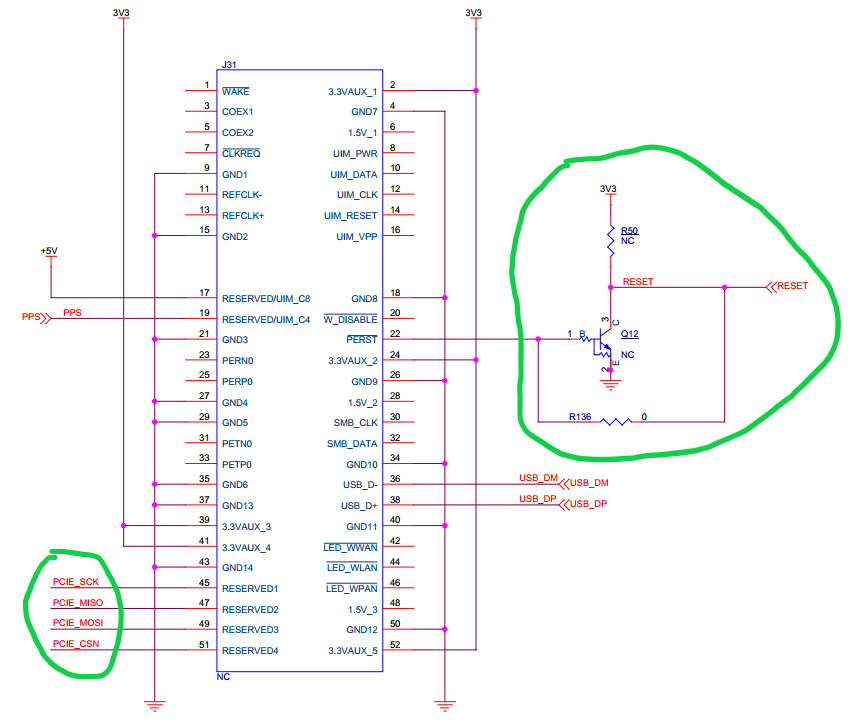
I see that on Pin 22 of the RAK2247 that the reset is active high.
It seems the Mini-PCIe spec uses active low for the reset.

What reasons was active high used? Even if the SX1301 requires a high reset, couldn’t an inverter have been used to more closely follow the Mini-PCIe spec to be compatible with most SBCs?

Is there perhaps a variant or modification that can be done so that a RAK2247 with active low reset could be used?

Thank you,
Ryan

Dear Ryan,

Please refer to the following picture(SCH).

For RAK2247,what we are used is only PCIe Form factor,not PCIe interface standard definition.So,usually the net connected to Pin22 is a GPIO from HOST,not PERST of PCIe interface.
Of course,we can populate R50 and Q12 and remove R136 if you want to use active low for the reset.But this kind of products need to be customized and we will deal with them before sending them to you.

By the way,do you use SPI or USB interface RAK2247?If you use USB interface RAK2247,you can reset SX1301 by USB(FT2232’s ADBUS5, remove R136).

Hello Jeff. Thank you so much for the reply.

We will be using USB, as the SBCs used conform to the Mini-PCIe spec, which has USB on it, but not SPI. So that sounds like a decent workaround.

It is very nice you added R50 and Q12 as an optional load (removing R136) as well.

We will consider these options and contact you directly for more moving forward.

Thank you,
Ryan

Hi @Jeff,
Can you explain a bit more on how to reset via the USB interface. Do we need to remove R136 from the board (Note you have circled R133 in you schematic screen grab)

I’m currently trying to get the RAK2247 USB to work with a x86 board.

Thanks.

1.Usually,Customers only use USB interface.No need to remove R136 because there is no connection to PIN22 of PCIe connector.
2.The USB to SPI IC is FT2232HL.You can set Pin22 of FT2232HL High to do reset if you have drivers of FT2232HL intergated in your X86 board.

Thanks Jeff,
Do you have a example of how you would do this with the correct drivers?

Currently lsusb give me:

$ lsusb
Bus 002 Device 001: ID 1d6b:0003 Linux Foundation 3.0 root hub
Bus 001 Device 004: ID 0403:6010 Future Technology Devices International, Ltd FT2232C Dual USB-UART/FIFO IC
Bus 001 Device 003: ID 0424:2514 Standard Microsystems Corp. USB 2.0 Hub
Bus 001 Device 002: ID 046d:c315 Logitech, Inc. Classic Keyboard 200
Bus 001 Device 001: ID 1d6b:0002 Linux Foundation 2.0 root hub

lsmod gives:

$ lsmod | grep ftdi
ftdi_sio               53248  0
usbserial              45056  1 ftdi_sio
$ uname --all
Linux gw01-test 4.15.0-66-generic #75-Ubuntu SMP Tue Oct 1 05:24:09 UTC 2019 x86_64 x86_64 x86_64 GNU/Linux

Hi Jeff,
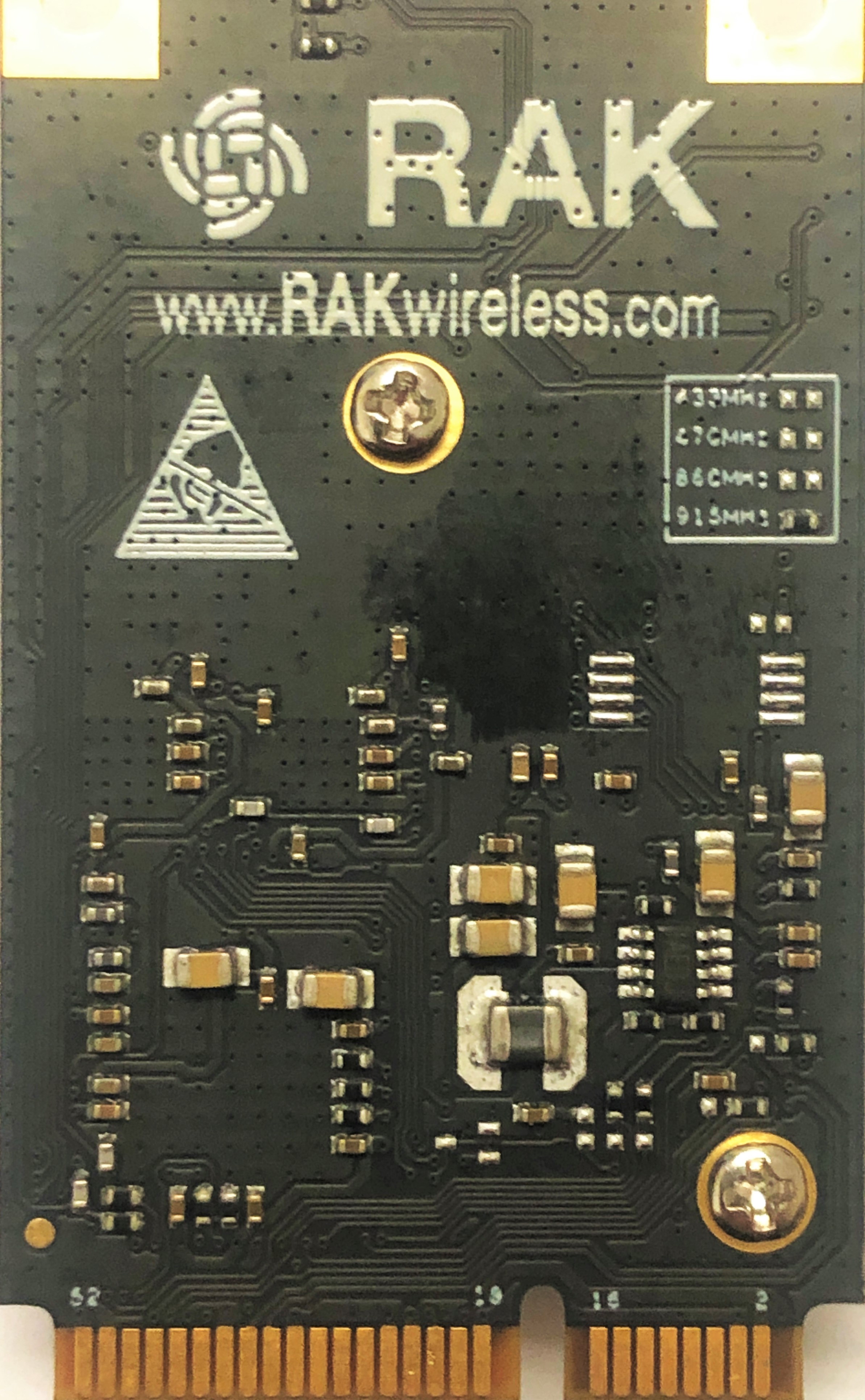
We have a card and want to modify the reset by removing R136 since our slot does have PCIe Reset mapped to that pin. Can you point out on the back of the card where R136 is (hopefully it’s not on topside with shield)? I was able to find the transistor that isn’t loaded near the large cap.

Thanks,

Ron

Hay @roneis,
As I read @Jeff answers if it is a USB only board, the PIC port pin 22 is not connected on the RAK board. But on another device where I can control PIC port pin 22 running the standard reset script allows lora_pkt_fwd to start the concentrator???.

But I push forward and am trying to reset through software and drive the ADBUS5 gpio High (FT2232HL pin 22).

I’m currently trying to do that with python (pyftdi)
Note this is still a work in progress and doesn’t solve the problem yet:

from os import environ
from time import sleep
from pyftdi.gpio import GpioController, GpioException

if __name__ == '__main__':
    gpio = GpioController()
    url = environ.get('FTDI_DEVICE', 'ftdi://ftdi:2232/1')
    # ADBUS0 | In | 0
    # ADBUS1 | In | 0
    # ADBUS2 | In | 0
    # ADBUS3 | In | 0
    # ADBUS4 | In | 0
    # ADBUS5 | Out | 1
    # ADBUS6 | In | 0
    # ADBUS6 | In | 0
    # 0000 0100 == 0x04
    mask = 0x04
    on = mask &= 0xFF
    off = mask &= 0x00
    gpio.open_from_url(url, direction=mask)
    print(gpio.read_port())
    gpio.write_port(off)
    print(gpio.read_port())
    sleep(0.1)
    gpio.write_port(on)
    print(gpio.read_port())
    sleep(0.1)
    gpio.write_port(off)
    print(gpio.read_port())
    gpio.close()

this output

255
251
255
251

so it looks like ADBUS5 is switching, but then running lora_pkt_fwd gives the same result :confused:

ERROR: Failed to load fw 1
ERROR: Version of calibration firmware not expected, actual:0 expected:2
ERROR: [main] failed to start the concentrator

to find your url use:

$ python3
Python 3.6.8 (default, Oct  7 2019, 12:59:55)
[GCC 8.3.0] on linux
Type "help", "copyright", "credits" or "license" for more information.
>>> from pyftdi.ftdi import Ftdi
>>> Ftdi().open_from_url('ftdi:///?')
Available interfaces:
  ftdi://ftdi:2232/1   (Dual RS232-HS)
  ftdi://ftdi:2232/2   (Dual RS232-HS)

Please specify the USB device

in my case ADBUS* gpio should be on ftdi://ftdi:2232/1

It’s unclear to me if the resistor that would connect the FT2232H to the SX1301 reset is normally installed, but if it is, you don’t need to write any python code to manipulate it, as the code in the FTDI-compatibility-reverted version of the lora gateway library already does that:

Your attempts would probably be undone by this anyway.

Also, don’t jump right to running the packet forwarder, run the spi tests from the lora gateway library first.

In one were desperate to disconnect the reset from the PCI bus, the picture in this thread shows a via right above the relevant edge finger, a moment with a drill bit twisted in ones fingers would break the connectivity, but that is likely to be fairly permanent. It’s possible you could get the card into a socket with a piece of kapton tape over the relevant finger(s) - likely not much nearby is needed.

Or consider putting the card in an external GSM modem mPCIE to USB adapter (just make sure the regulator isn’t set to output an unusually high voltage, as many of the cheap ones seem to be)

1 Like

Thanks @cstratton,
You got me thinking and I did some digging in the rakwireless github and found that yes you are right even in the “rak_common_for_gateway” version they are toggling ADBUS5

also found how to switch on debug

and switching all debugs on I can see its reading/writing SPI but stiff fails to start

$ sudo ./lora_pkt_fwd
*** Beacon Packet Forwarder for Lora Gateway ***
Version: 4.0.1
*** Lora concentrator HAL library version info ***
Version: 5.0.1;
***
INFO: Little endian host
INFO: found global configuration file global_conf.json, parsing it
INFO: global_conf.json does contain a JSON object named SX1301_conf, parsing SX1301 parameters
INFO: lorawan_public 1, clksrc 1
lgw_board_setconf:427: Note: board configuration; lorawan_public:1, clksrc:1
INFO: LBT is disabled
INFO: antenna_gain 0 dBi
INFO: Configuring TX LUT with 16 indexes
INFO: radio 0 enabled (type SX1257), center frequency 867500000, RSSI offset -166.000000, tx enabled 1, tx_notch_freq 129000
lgw_rxrf_setconf:488: Note: rf_chain 0 configuration; en:1 freq:867500000 rssi_offset:-166.000000 radio_type:2 tx_enable:1 tx_notch_freq:129000
INFO: radio 1 enabled (type SX1257), center frequency 868500000, RSSI offset -166.000000, tx enabled 0, tx_notch_freq 0
lgw_rxrf_setconf:488: Note: rf_chain 1 configuration; en:1 freq:868500000 rssi_offset:-166.000000 radio_type:2 tx_enable:0 tx_notch_freq:0
INFO: Lora multi-SF channel 0>  radio 1, IF -400000 Hz, 125 kHz bw, SF 7 to 12
lgw_rxif_setconf:607: Note: LoRa 'multi' if_chain 0 configuration; en:1 freq:-400000 SF_mask:0x7e
INFO: Lora multi-SF channel 1>  radio 1, IF -200000 Hz, 125 kHz bw, SF 7 to 12
lgw_rxif_setconf:607: Note: LoRa 'multi' if_chain 1 configuration; en:1 freq:-200000 SF_mask:0x7e
INFO: Lora multi-SF channel 2>  radio 1, IF 0 Hz, 125 kHz bw, SF 7 to 12
lgw_rxif_setconf:607: Note: LoRa 'multi' if_chain 2 configuration; en:1 freq:0 SF_mask:0x7e
INFO: Lora multi-SF channel 3>  radio 0, IF -400000 Hz, 125 kHz bw, SF 7 to 12
lgw_rxif_setconf:607: Note: LoRa 'multi' if_chain 3 configuration; en:1 freq:-400000 SF_mask:0x7e
INFO: Lora multi-SF channel 4>  radio 0, IF -200000 Hz, 125 kHz bw, SF 7 to 12
lgw_rxif_setconf:607: Note: LoRa 'multi' if_chain 4 configuration; en:1 freq:-200000 SF_mask:0x7e
INFO: Lora multi-SF channel 5>  radio 0, IF 0 Hz, 125 kHz bw, SF 7 to 12
lgw_rxif_setconf:607: Note: LoRa 'multi' if_chain 5 configuration; en:1 freq:0 SF_mask:0x7e
INFO: Lora multi-SF channel 6>  radio 0, IF 200000 Hz, 125 kHz bw, SF 7 to 12
lgw_rxif_setconf:607: Note: LoRa 'multi' if_chain 6 configuration; en:1 freq:200000 SF_mask:0x7e
INFO: Lora multi-SF channel 7>  radio 0, IF 400000 Hz, 125 kHz bw, SF 7 to 12
lgw_rxif_setconf:607: Note: LoRa 'multi' if_chain 7 configuration; en:1 freq:400000 SF_mask:0x7e
INFO: Lora std channel> radio 1, IF -200000 Hz, 250000 Hz bw, SF 7
lgw_rxif_setconf:581: Note: LoRa 'std' if_chain 8 configuration; en:1 freq:-200000 bw:2 dr:2
INFO: FSK channel> radio 1, IF 300000 Hz, 125000 Hz bw, 50000 bps datarate
lgw_rxif_setconf:637: Note: FSK if_chain 9 configuration; en:1 freq:300000 bw:3 dr:50000 (50000 real dr) sync:0xC194C1
INFO: global_conf.json does contain a JSON object named gateway_conf, parsing gateway parameters
INFO: gateway MAC address is configured to AA555A0000000000
INFO: server hostname or IP address is configured to "localhost"
INFO: upstream port is configured to "1680"
INFO: downstream port is configured to "1680"
INFO: downstream keep-alive interval is configured to 10 seconds
INFO: statistics display interval is configured to 30 seconds
INFO: upstream PUSH_DATA time-out is configured to 100 ms
INFO: packets received with a valid CRC will be forwarded
INFO: packets received with a CRC error will NOT be forwarded
INFO: packets received with no CRC will NOT be forwarded
INFO: found local configuration file local_conf.json, parsing it
INFO: redefined parameters will overwrite global parameters
INFO: local_conf.json does not contain a JSON object named SX1301_conf
INFO: local_conf.json does contain a JSON object named gateway_conf, parsing gateway parameters
INFO: gateway MAC address is configured to 0001C0FFFE25D014
INFO: packets received with a valid CRC will be forwarded
INFO: packets received with a CRC error will NOT be forwarded
INFO: packets received with no CRC will NOT be forwarded
lgw_spi_open:88: SPI port opened and configured ok
desc: (null)
PID: 0x6010
VID: 0x0403
clock: 6000000
Libmpsse version: 0x13
Note: SPI read success
lgw_connect:532: INFO: no FPGA detected or version not supported (v103)
Note: SPI read success
Note: SPI write success
Note: success connecting the concentrator
Note: SPI write success
Note: SPI read success
Note: SPI write success
Note: SPI read success
Note: SPI write success
Note: SPI read success
Note: SPI write success
Note: SPI read success
Note: SPI write success
Note: SPI read success
Note: SPI write success
Note: SPI read success
Note: SPI write success
Note: SPI read success
Note: SPI write success
Note: SPI read success
Note: SPI write success
Note: SPI read success
Note: SPI write success
Note: SPI read success
lgw_setup_sx125x:407: Note: SX125x #0 version register returned 0x07
Note: SPI read success
Note: SPI write success
Note: SPI read success
Note: SPI write success
Note: SPI read success
Note: SPI write success
lgw_setup_sx125x:415: Note: SX125x #0 clock output disabled
Note: SPI read success
Note: SPI write success
Note: SPI read success
Note: SPI write success
Note: SPI read success
Note: SPI write success
Note: SPI read success
Note: SPI write success
Note: SPI read success
Note: SPI write success
Note: SPI read success
Note: SPI write success
Note: SPI read success
Note: SPI write success
Note: SPI read success
Note: SPI write success
Note: SPI read success
Note: SPI write success
Note: SPI read success
Note: SPI write success
Note: SPI read success
Note: SPI write success
Note: SPI read success
Note: SPI write success
Note: SPI read success
Note: SPI write success
Note: SPI read success
Note: SPI write success
Note: SPI read success
Note: SPI write success
Note: SPI read success
Note: SPI write success
Note: SPI read success
Note: SPI write success
Note: SPI read success
Note: SPI write success
Note: SPI read success
Note: SPI write success
Note: SPI read success
Note: SPI write success
Note: SPI read success
Note: SPI write success
Note: SPI read success
Note: SPI write success
Note: SPI read success
Note: SPI write success
Note: SPI read success
Note: SPI write success
Note: SPI read success
Note: SPI write success
Note: SPI read success
Note: SPI write success
Note: SPI read success
Note: SPI write success
Note: SPI read success
Note: SPI write success
Note: SPI read success
Note: SPI write success
Note: SPI read success
Note: SPI write success
Note: SPI read success
Note: SPI write success
Note: SPI read success
Note: SPI write success
Note: SPI read success
Note: SPI write success
Note: SPI read success
Note: SPI write success
Note: SPI read success
Note: SPI write success
Note: SPI read success
Note: SPI write success
lgw_setup_sx125x:469: Note: SX125x #0 PLL start (attempt 1)
Note: SPI read success
Note: SPI write success
Note: SPI read success
Note: SPI write success
Note: SPI read success
Note: SPI write success
Note: SPI read success
Note: SPI write success
Note: SPI read success
Note: SPI write success
Note: SPI read success
Note: SPI write success
Note: SPI read success
lgw_setup_sx125x:407: Note: SX125x #1 version register returned 0x1f
Note: SPI read success
Note: SPI write success
Note: SPI read success
Note: SPI write success
Note: SPI read success
Note: SPI write success
lgw_setup_sx125x:412: Note: SX125x #1 clock output enabled
Note: SPI read success
Note: SPI write success
Note: SPI read success
Note: SPI write success
Note: SPI read success
Note: SPI write success
Note: SPI read success
Note: SPI write success
Note: SPI read success
Note: SPI write success
Note: SPI read success
Note: SPI write success
Note: SPI read success
Note: SPI write success
Note: SPI read success
Note: SPI write success
Note: SPI read success
Note: SPI write success
Note: SPI read success
Note: SPI write success
Note: SPI read success
Note: SPI write success
Note: SPI read success
Note: SPI write success
Note: SPI read success
Note: SPI write success
Note: SPI read success
Note: SPI write success
Note: SPI read success
Note: SPI write success
Note: SPI read success
Note: SPI write success
Note: SPI read success
Note: SPI write success
Note: SPI read success
Note: SPI write success
Note: SPI read success
Note: SPI write success
Note: SPI read success
Note: SPI write success
Note: SPI read success
Note: SPI write success
Note: SPI read success
Note: SPI write success
Note: SPI read success
Note: SPI write success
Note: SPI read success
Note: SPI write success
Note: SPI read success
Note: SPI write success
Note: SPI read success
Note: SPI write success
Note: SPI read success
Note: SPI write success
Note: SPI read success
Note: SPI write success
Note: SPI read success
Note: SPI write success
Note: SPI read success
Note: SPI write success
Note: SPI read success
Note: SPI write success
Note: SPI read success
Note: SPI write success
Note: SPI read success
Note: SPI write success
Note: SPI read success
Note: SPI write success
Note: SPI read success
Note: SPI write success
Note: SPI read success
Note: SPI write success
lgw_setup_sx125x:469: Note: SX125x #1 PLL start (attempt 1)
Note: SPI read success
Note: SPI write success
Note: SPI read success
Note: SPI write success
Note: SPI read success
Note: SPI write success
Note: SPI read success
Note: SPI write success
Note: SPI read success
Note: SPI write success
Note: SPI read success
Note: SPI write success
Note: SPI read success
Note: SPI write success
Note: SPI read success
Note: SPI write success
Note: SPI read success
Note: SPI write success
Note: SPI burst write success
Note: SPI read success
Note: SPI burst read success
ERROR: Failed to load fw 1
Note: SPI read success
Note: SPI write success
Note: SPI read success
Note: SPI write success
Note: SPI read success
ERROR: Version of calibration firmware not expected, actual:0 expected:2
ERROR: [main] failed to start the concentrator

Don’t know what spi test you where referring to but I ran the default “util_spi_stress” and got

$ sudo ./util_spi_stress/util_spi_stress
INFO: Starting LoRa concentrator SPI stress-test number 1
Cycle 0 > error during the 1th iteration: write 0x67, read 0x00
Repeat read of target register: 0x00 0x00 0x00 0x00 0x00 0x00 0x00 0x00 0x00 0x00 0x00 0x00 0x00 0x00 0x00 0x00

assuming this is not the expected output of a working device, currently googling to see what i can find

Thanks for your pointers and help.

Just following up,
@cstratton I did get desperate and took a moment with the drill and once disconnect everything worked.

@Jeff it would be nice to know where R136 is located on the board so we can remove it when using the board in a mPICe slot.

anyways log of working Lora Packet Forwarder:

$ sudo ./lora_pkt_fwd
*** Beacon Packet Forwarder for Lora Gateway ***
Version: 4.0.1
*** Lora concentrator HAL library version info ***
Version: 5.0.1;
***
INFO: Little endian host
INFO: found global configuration file global_conf.json, parsing it
INFO: global_conf.json does contain a JSON object named SX1301_conf, parsing SX1301 parameters
INFO: lorawan_public 1, clksrc 1
INFO: LBT is disabled
INFO: antenna_gain 0 dBi
INFO: Configuring TX LUT with 16 indexes
INFO: radio 0 enabled (type SX1257), center frequency 867500000, RSSI offset -166.000000, tx enabled 1, tx_notch_freq 129000
INFO: radio 1 enabled (type SX1257), center frequency 868500000, RSSI offset -166.000000, tx enabled 0, tx_notch_freq 0
INFO: Lora multi-SF channel 0>  radio 1, IF -400000 Hz, 125 kHz bw, SF 7 to 12
INFO: Lora multi-SF channel 1>  radio 1, IF -200000 Hz, 125 kHz bw, SF 7 to 12
INFO: Lora multi-SF channel 2>  radio 1, IF 0 Hz, 125 kHz bw, SF 7 to 12
INFO: Lora multi-SF channel 3>  radio 0, IF -400000 Hz, 125 kHz bw, SF 7 to 12
INFO: Lora multi-SF channel 4>  radio 0, IF -200000 Hz, 125 kHz bw, SF 7 to 12
INFO: Lora multi-SF channel 5>  radio 0, IF 0 Hz, 125 kHz bw, SF 7 to 12
INFO: Lora multi-SF channel 6>  radio 0, IF 200000 Hz, 125 kHz bw, SF 7 to 12
INFO: Lora multi-SF channel 7>  radio 0, IF 400000 Hz, 125 kHz bw, SF 7 to 12
INFO: Lora std channel> radio 1, IF -200000 Hz, 250000 Hz bw, SF 7
INFO: FSK channel> radio 1, IF 300000 Hz, 125000 Hz bw, 50000 bps datarate
INFO: global_conf.json does contain a JSON object named gateway_conf, parsing gateway parameters
INFO: gateway MAC address is configured to AA555A0000000000
INFO: server hostname or IP address is configured to "localhost"
INFO: upstream port is configured to "1680"
INFO: downstream port is configured to "1680"
INFO: downstream keep-alive interval is configured to 10 seconds
INFO: statistics display interval is configured to 30 seconds
INFO: upstream PUSH_DATA time-out is configured to 100 ms
INFO: packets received with a valid CRC will be forwarded
INFO: packets received with a CRC error will NOT be forwarded
INFO: packets received with no CRC will NOT be forwarded
INFO: found local configuration file local_conf.json, parsing it
INFO: redefined parameters will overwrite global parameters
INFO: local_conf.json does not contain a JSON object named SX1301_conf
INFO: local_conf.json does contain a JSON object named gateway_conf, parsing gateway parameters
INFO: gateway MAC address is configured to 0001C0FFFE25D014
INFO: packets received with a valid CRC will be forwarded
INFO: packets received with a CRC error will NOT be forwarded
INFO: packets received with no CRC will NOT be forwarded
INFO: [main] concentrator started, packet can now be received

INFO: Disabling GPS mode for concentrator's counter...
INFO: host/sx1301 time offset=(1573853275s:871591µs) - drift=1573853275871591µs
INFO: Enabling GPS mode for concentrator's counter.


##### 2019-11-15 21:28:28 GMT #####
### [UPSTREAM] ###
# RF packets received by concentrator: 0
# CRC_OK: 0.00%, CRC_FAIL: 0.00%, NO_CRC: 0.00%
# RF packets forwarded: 0 (0 bytes)
# PUSH_DATA datagrams sent: 0 (0 bytes)
# PUSH_DATA acknowledged: 0.00%
### [DOWNSTREAM] ###
# PULL_DATA sent: 3 (0.00% acknowledged)
# PULL_RESP(onse) datagrams received: 0 (0 bytes)
# RF packets sent to concentrator: 0 (0 bytes)
# TX errors: 0
# BEACON queued: 0
# BEACON sent so far: 0
# BEACON rejected: 0
### [JIT] ###
# SX1301 time (PPS): 2676327
src/jitqueue.c:448:jit_print_queue(): INFO: [jit] queue is empty
### [GPS] ###
# GPS sync is disabled
##### END #####

JSON up: {"stat":{"time":"2019-11-15 21:28:28 GMT","rxnb":0,"rxok":0,"rxfw":0,"ackr":0.0,"dwnb":0,"txnb":0}}

Thanks for the help, a software solution would have been nice.