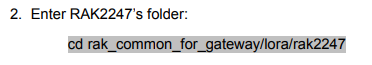
Please confirm that it is in the rak2247 directory.
Thanks for your reply, in the step 5, you have an error in the PDF. In the document you’ve written:
cp …/set_dui.sh packet_forwarder/lora_pkt_fwd
and it should be read (with an e)
cp …/set_eui.sh packet_forwarder/lora_pkt_fwd
could you please send me a private email to check some questions?
Oh, yes, this is an written error. It should be ‘e’ not ‘d’. We’ll modify immediately.
Thank you very much!
Following updated guide, I am able to install scripts.
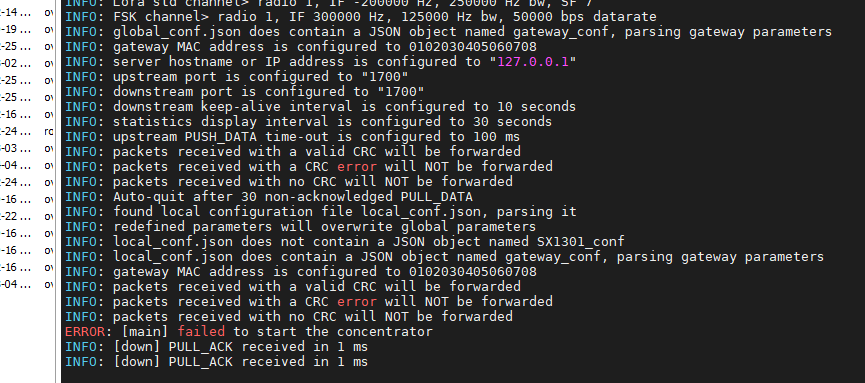
However, upon executing lora_pkt_fwd, I am receiving errors:
ERROR: Failed to load fw 1
ERROR: Version of calibration firmware not expected, actual:0 expected:2
ERROR: [main] failed to start the concentrator
Can anyone advise as to the issue?
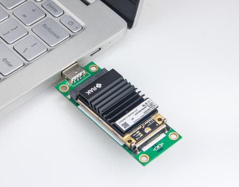
RAK2247 has two kinds of hardware, although they are both mPCIe interface. What’s your RAK2247 module? SPI or USB?
Only the USB one can be used on X86 Linux PC now, and it need a mPCIe2USB convert boart as the following picture shows:
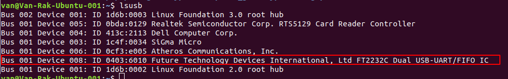
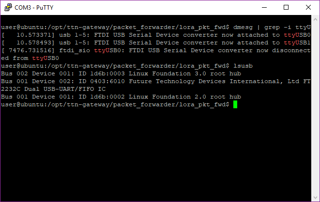
I have the RAK2247 installed into our system, which has mPCIe interface with only USB 3.0 signalling. When calling lsusb I am able to see the UART FTDI device.
Do you believe this to be a HW related issue?
I need more information before and after this message.
![]()
Not too sure what happened there, left device idle. Don’t believe it is related.
[ 11.291848] Adding 1909756k swap on /dev/sda5. Priority:-1 extents:1 across:1909756k SSFS
[ 11.710240] cgroup: new mount options do not match the existing superblock, will be ignored
[ 11.995483] squashfs: version 4.0 (2009/01/31) Phillip Lougher
[ 7461.694817] igb 0000:01:00.0 enp1s0: igb: enp1s0 NIC Link is Up 1000 Mbps Full Duplex, Flow Control: RX/TX
[ 7461.695019] IPv6: ADDRCONF(NETDEV_CHANGE): enp1s0: link becomes ready
[ 7476.731516] ftdi_sio ttyUSB0: FTDI USB Serial Device converter now disconnected from ttyUSB0
[ 7476.731747] ftdi_sio 1-5:1.0: device disconnected
user@ubuntu:/opt/ttn-gateway/packet_forwarder/lora_pkt_fwd$
Okay. So, re-installed OS, then followed instructions again. Seems like it is working now. I will need to modify the address from router.us.thethings.network apparently…
ERROR: [up] getaddrinfo on address router.us.thethings.network (PORT 1700) returned Temporary failure in name resolution
On TTN, its recommending ttn-router-us-west. What do I need to do to implement this change?
Hi @hfung
Did you change something in global_conf.json?
The “url” is router.us.thethings.network . ttn-router-us-west is load balancer for this region, not address.
Regards
Todor Velev
Hi Velev, settings have been left with defaults.
So, I’m back to my original predicament… what I am seeing now, again, is:
ERROR: Failed to load fw 1
ERROR: Version of calibration firmware not expected, actual:0 expected:2
ERROR: [main] failed to start the concentrator
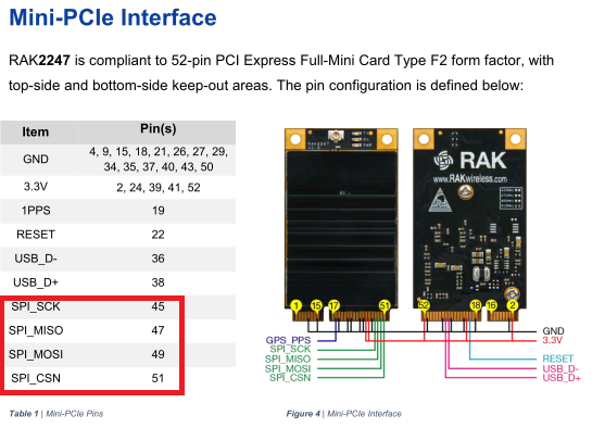
Since I am having the USB mPCIe SKU - are the following signal required?
Anyone from RAKwireless able to comment on this please?
My outsider’s understanding is that not only would you not use the SPI pins if making a USB connection, but that unlike the RAK833 which had a multiplexer, if you purchase a USB model of the RAK2247 the SPI pins are not even connected to anything, so you could not use them even if you wanted to.
It’s less clear if you are supposed to reset the SX1301 via the pcie PERST# signal on pin 22, or if that is done through the FTDI USB-SPI bridge.
If you are supposed to reset it explicitly, I believe the signal is high to reset and low to run (as it is on the actual SX1301 chip), which would be opposite the pcie standard of low to reset and high to run.
Hopefully you can get official clarification.
Make sure the mini-pcie PERST# signal(pin 22) pulled down (default high will cause rak833 function error)
Has anyone been able to get clarification on this?
It’s less clear if you are supposed to reset the SX1301 via the pcie PERST# signal on pin 22, or if that is done through the FTDI USB-SPI bridge.
If you are supposed to reset it explicitly, I believe the signal is high to reset and low to run (as it is on the actual SX1301 chip), which would be opposite the pcie standard of low to reset and high to run.