RAK2270 Sticker Tracker Nov 2023 update

@carlrowan Awesome, yes the Sparkfun LIS3DH examples work great on the RAK2270 Sticker Tracker easy to load the fullExample and get x,y,z every second.

If you can get from the techs:

Pads 1-7
How to reset (I assume RST to ground)
How to put into boot mode ( I assume Boot0 to ground twice)
Is 5V input VCC from USB ok to use? Much easier than connecting 3.3 V

I am presently checking out CayenneLPP. I am not sure if the data is getting sent properly.

Ok. I am learning a ton about RAK AT commands.

Note: ? is for help
= set (be very careful)
=? get or show the value

AT? is very useful all the commands

ATE Description: AT Command Echo

ATZ Description: MCU Reset

AT+BOOT Description: Bootloader mode

AT+RUN will reset from bootloader mode. (similar to AT+RESET)

AT+DEVEUI=? Description: Device EUI

AT+APPEUI=? Description: Application identifier

AT+APPKEY=? Description: Application Key

AT+JOIN Description: Join LoRaWAN Network (wait a few seconds after the OK. )

AT+NJM=? Description: Network Join Mode (0 = ABP, 1 = OTAA)|

AT+NJS=? Description: LoRa Network Join status(0 = not joined, 1 = joined)|

AT+RECV=? Description: Last received data in hex mode (not working for me)

AT+SEND=12:112233   Send data in port: hex format (not working for me)

AT+CLASS=? Description: LoRa Class A B or C

AT+TXP=?: transmitting power (0 = highest TX power, 14 = lowest TX power) lowest is different

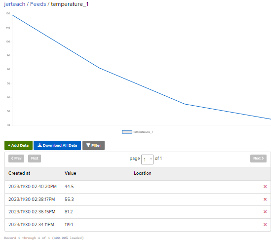
AT+RSSI=?  Gives the RSSI strength of the last connection

AT+ARSSI=? Description: Inquire all channel RSSI

AT+MASK=? Description: Set the channel mask, close or open the channel


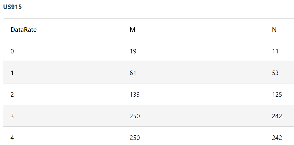
AT+BAND=?	Description: Active region
(0 = EU433, 1 = CN470, 2 = RU864, 3 = IN865, 4 = EU868,
5 = US915, 6 = AU915, 7 = KR920, 8 = AS923-1, 9 = AS923-2, 10 = AS923-3, 11 = AS923-4, 12 = LA915)


There are a ton more AT commands. Does anyone else know about any that are really useful.

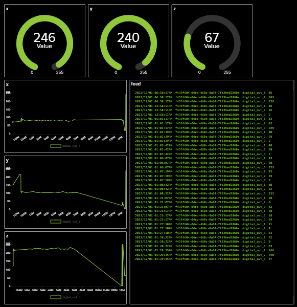
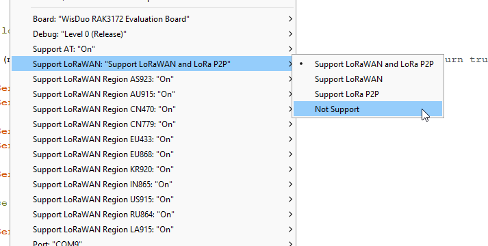
The P2P AT commands also look interesting.

AT+NWM=?  Description: LoRa network work mode[0:Point-to-point, 1:LoRaWAN].

Hi Jeremy,

  1. Pads 1-7 - I’ll update you once I got a word from the team.
  2. Reset - Correct. If RST goes to GND, the chip will reset.
  3. Boot Mode - This Boot pin is the default functionality of STM32 chip. Twice tap to ground has no meaning. This needs to be pulled-up then reset so that the device will proceed to UART bootloader of STM32. This needs STM32CubeIDE.
  4. NO! The battery is directly connected to chip. Max is 3.6v. If you put 5V, it will likely work for while but we do not know when it will start to fail.
  5. CayenneLPP. The Cayenna library works ok. You can easily test this in TTN since it has Cayenne option by default.

Thaks Again @carlrowan

That explains a lot.and the RAK AT commands are so good I don’t think I have to go down that path again. By the way if I was to try programming the LoRa module like I have done with he Arduino PortentaH7 with LoRa vision shield using GitHub - GrumpyOldPizza/ArduinoCore-stm32l0: Arduino Core for STM32L0
my code is here but would probably need a lot of changes to get pure LoRa working on the RAK2270 sticker tracker.

As I said the RAK AT commands are very powerful so presently I would have no reason to code the module.

That does bring up one question. How on the board do I force typical BOOT mode, not the STM32 boot?

Any suggestions? I know the AT command

AT+BOOT should work and AT+RUN should remove it but from a hardware point of view do you have suggestions.

Finally I got CayenneLPP fake data sent to Helium and then to Adafruit.io

Took a ridiculous amount of time. Not really sure why.

image

My Github for code is here

1 Like

We have pin that forces boot mode before but this causes issues so we remove it.

There is no physical way to do it at the moment.

Besides, uploading of new firmware is done via UART so if there is be a software doing the uploading of new firmware, the software needs to issue an AT+BOOT first.

1 Like

I uploaded now the file for testpoints. You can check it together with test testpoints label in the datasheet.

Testpoints
Schematic

No Problem. I find your software on the Arduino IDE is fairly good at forcing boot mode. Also the AT command AT+BOOT makes it slightly faster.

@carlrowan that pin mapping is super useful I will have a new image with pins soon. I am doing well with the accelerometer. Here is an adafruit.io dashboard showing the accelerometer setting converted to 0-255 bytes where 255 would be about 4 G’s. I am very pleased this is working.

Really important for people to realize that for me at least this 11 byte AT command works but this 12 byte AT command does not work, and doing an AT+LPSEND is actually sending a few packets so it makes things more complex

AT+SEND=5:112233445566778899AABB These 11 bytes send easily
AT+SEND=5:112233445566778899AABBCC These 12 bytes do not send

but
AT+LPSEND=5:0:112233445566778899AABBCC Sends as 2 or more packets which does seem to confuse Helium and CayenneLPP

Just thought I should mention that.

Note: These commands are used in code as

api.lorarwan.send() or api.lorawan.lpsend()

LoRaQWan and Helium have data limits which is fine for a working product but is horrible for testing. I think the next step is to mess around with both Machine Learning and P2P. If anyone has opinions on the best P2P AT commands please post them.

I have done some p2p work with the Arduino portentaH7 so I am curious if RAK has done any MESH style P2P LoRa connectivity?

What is your region and what is the datarate.
E.g. in US915 at DR0 your payload is limited to 11 bytes.
Max payload per datarate and region

lpsend works only with RAK Edge gateways like the RAK7268 and the internal network server.

@carlrowan

Thanks @beegee. Yes, for US915 the chart is

The chart is 11 bytes at the default Datarate. I could do some testing with changing the datarate but my bigger problem is that my machine leaning library here and EdgeImpulse’s ML libraries do not run on the device. For both I am getting an error about the size of the ROM.

Possibly the standard ML program is trying to save data into the wrong location. Anyone know the amount of ROM and flash in the RAK2270 Sticker Tracker, compared to say a XIAO SAMD (32KB SRAM, 256KB Flash ) or Arduino Nano33BleSense (256 KB SRAM, 1MB flash)?

From RAK3172 ROM overflowed - #2 by beegee

looks like it is 250kb flash

from here https://soyter.pl/en/products/rakwireless-rak3172-eu868-evaluation-board-evaluation-board-4999.html?query_id=2

RAK3172 evaluation board which is similar
ARM Cortex-M4 32-bit
64 kbytes RAM
256 kbytes flash memory with ECC

Looks like anything that runs on the XIAO SAMD board should run on the RAK2270. I will do a bit more testing.


Side note: Is the battery on the sticker tracker’s rechargeable? If so, does anyone know the typical charge rate, current and voltage for them?

@beegee It looks like the RUI firmware takes up a bit of space. I tried the simplest machine learning code the sine wave and it ran on the XIAO SAMD but was 76K short for the RAK2270 sticker tracker.

Too bad. Without ML ability I will probably have to find something else.

Here is the error message. It looks like it was simply out of memory.

.../.././arduino_build_454572/SineExample.ino.elf section `.text' will not fit in region `ROM'
 region `ROM' overflowed by 76216 bytes
collect2: error: ld returned 1 exit status
Using library RocksettaTinyML-master at version 0.0.2 in folder:..Arduino/libraries/RocksettaTinyML-master
exit status 1
Error compiling for board WisDuo RAK3172 Evaluation Board.

Hi @jerteach ,

The battery of RAK2270 is non-rechargeable. It’s Li-MnO2 voltage with voltage level that will stay around 3V in most of its useful life. Capacity is 600mAh. Specific PN is CP145550.

With regards to memory, RUI3 surely occupies memory space with all the features it squeeze on the chip (AT command, API for LoRaWAN/LoRa, Arduino lib support, encryption, etc.)

You might still be able to squeeze if you disable some functions which is supported now by the latest RUI3 firmware. You can even turn off both LoRaWAN/LoRa functions (but might not make sense since it is a LoRa module).

:grinning: @carlrowan I thought I was done with the RAK2270 Sticker Tracker and then you pulled me back in :grinning:

Not sure why I didn’t see those settings. Here are my results for the very simple Sine Wave my version of the Hello World Tensorflow type Machine Learning Program:

After turning off LoRaWan and P2P
Sketch uses 143888 bytes (71%) of program storage space. Maximum is 200704 bytes.
Global variables use 25840 bytes (53%) of dynamic memory, leaving 22800 bytes for local variables. Maximum is 48640 bytes.

And it actually goes fairly fast on the Arduino Plotter screen.

After also as above and turning OFF all LoRaWan regions except US915 the memory was:

No Change
Sketch uses 143888 bytes (71%) of program storage space. Maximum is 200704 bytes.
Global variables use 25840 bytes (53%) of dynamic memory, leaving 22800 bytes for local variables. Maximum is 48640 bytes.

After turning back on only LoRaWan not P2P I get

region `ROM’ overflowed by 35848 bytes. THAT IS A CONCERN!

After turning off LoRaWan and turning on P2P I get

Sketch uses 164552 bytes (81%) of program storage space. Maximum is 200704 bytes.
Global variables use 27168 bytes (55%) of dynamic memory, leaving 21472 bytes for local variables. Maximum is 48640 bytes.

The sine wave means nothing if an acceleration program doesn’t work, but I fired up the NiclaVision ML program a two label motion ML model and it loaded with 88% of memory used. So now I just have to convert that model over to the IMU used by the Sticker Tracker. It only works for P2P but I have a lot of faith in P2P for large onsite companies and Farms.

I also assume a P2P to LoRaWan device would not be that hard to make, but I have never done it. Does anyone have any ideas about that? The P2P collects several results and then hourly uploads a byte to a LoRaWan network, giving you 255 possible outcomes such as: 0 = All Good, 1= issue with the … 2= issues with the…, 3=…

I will post again eventually.

@carlrowan @beegee I need help with one thing. SerialRead(). The standard Serial.read example given for the RAK3172-SIP and you switch between Serial and Serial1 doesn’t work with the RAK2270 because you don’t have USB Serial and UART TX RX Serial, you only have UART TX, RX serial. Any suggestions how I can input from the keyboard with the RAK2270 Sticker Tracker? The chip has a second TX, RX line but I don’t have access to it.

Am I missing something. I even tried turning off “AT” commands but they strangely still worked. The best scenario would be that I could do SerialRead and “AT” commands. Any suggestions?

UPDATE: I am able to make Machine Learning models without SerialRead but I am really curious if the Sticker Tracker can do serialRead.


P.S. I did get a machine learning motion model working with P2P compiled for 2 labels. I will test if more labels are possible. The strange part is I got working my 3 year old model based on Eloquent Arduino, but could not get the more modern EdgeImpulse motion model working. It was about 40 K memory short even with all LoRaWan and P2P options disabled

Hi @jerteach ,

Glad to hear your tiny ML model works.

As for Serial.read, this is supported by RUI3. Here’s the documentation.

1 Like

@carlrowan

Oops That’s a dangerous bit of code. My Rak2270 Sticker Tracker was using AT+BOOT to get into boot mode to upload code. Basically the code below just bricked my board, since it effectively turns off AT commands and now the board can’t automatically get into boot mode. I think we already covered that there is no pin combination that forces boot mode.~

Much safer to use :

Serial.begin(115200, RAK_AT_MODE);
void setup() {
  Serial.begin(115200, RAK_CUSTOM_MODE);
}

void loop() {
  //print if you receive data
  if (Serial.available() > 0) {
    Serial.print("Return Byte = ");
    Serial.println(Serial.read());
  }
}

See comments below.

Hi @jerteach ,

AT+BOOT should still work with RAK_CUSTOM_MODE.

As you see here, I sent AT first (65 and 84) followed by AT+BOOT that’s why there is <BOOT MODE> in the image.

I can reupload firmware successfully even with RAK_CUSTOM_MODE.

Thanks @carlrowan after a bit that did work I will edit the comments above. What kind of worked for me was a space before the AT+BOOT.

I think I will work on that code to tidy it up. It needs to echo the AT commands but ATE seems to have no effect also AT seems not to show the regular “OK”

I will see what I can do.

That did make me get working on my other 2 stickers. With a heat gun to about 90 degrees Celsius the wrapper came off very easy, then just de-solder the battery positive terminal and place a bit of tape below it. Video coming soon. I still need to make a pogoPin arraignment since that hot-glue stuff looks terrible.

image

@carlrowan I prefer this code much better for the RAK2270 sticker tracker. It shows what you enter and runs the AT commands and allows other entries. I will be able to use this. Thanks for setting me on the correct path.

void setup() {
 // Serial.begin(115200, RAK_CUSTOM_MODE);
  Serial.begin(115200, RAK_AT_MODE);
}

void loop() {

   while(Serial.available() > 0) {
    char myChar = Serial.read();
    Serial.print(myChar);
  }
  
}