Anyone go information about the RAK2270 Sticker Trackers? Is there any way to get Device EUI information from RAKwireless by sending them the QR code?
Do I have to hack the stickers to set ort get the Device EUI?

Anyone go information about the RAK2270 Sticker Trackers? Is there any way to get Device EUI information from RAKwireless by sending them the QR code?
Do I have to hack the stickers to set ort get the Device EUI?
Hi @jerteach ,
Just send me the serial number (or QR code) via private message and I can check in our system.
If ever you proceed on prototyping by accessing the UART pins, you can get it via AT+DEVEUI=? as well.
I don’t think I have been on the forum long enough to be able to message people. On my other forums a message button shows up when I click the users name. Can you message me? Then I can send you all three of my Sticker Trackers QR codes.
Yes, when I get my UART connection finding the 3 keys should be easy using AT commands…
I posted an issue on the RAK2270 Github wondering if we could see the firmware installed on the stickers. I am mainly curious to see example code but also to see if any ability to set the upload data rate by reading a download code.
I am trying to determine if the RAK2270 Sticker Tracker is a good fit for Advanced High School IOT classrooms or University IOT programs. The price is perfect.
The best documentation seems to be at RAK3272-SiP-Breakout-Board for everything except the accelerometer.
I can now find the devEUI, appEUI and appKey. I can connect to the RAK2270 Sticker Tracker using a USB TTL connector. I can connect to the Helium Network. I can code some of it using the Arduino IDE Version2x but the installation only worked on one of my windows computers (The board Rakwireless RUI STM32 Boards does not show up when you search for “RAK”) using the .json link:
https://raw.githubusercontent.com/RAKwireless/RAKwireless-Arduino-BSP-Index/main/package_rakwireless.com_rui_index.json
Note: The installation works fine on Ubuntu Linux.
AT commands work great, mainly AT? AT+JOIN and AT+DEVEUI=? etc
Not sure why there isn’t an AT command for setting the antenna. Mine just seems to work with US915 but I have not found the setting in any of my code.
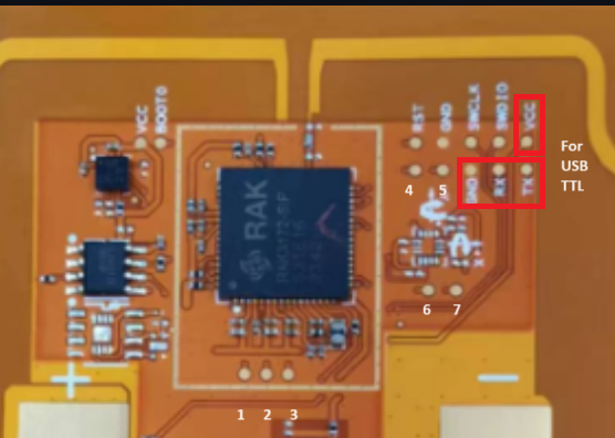
I would appreciate a pinout diagram, but can probably figure it out with some trial and error.
I was really worried about the VCC input from the TTL cable but it seems to be fine. I originally used 3.3 volts from another microcontroller, but the TTL power seems to work. No magic smoke yet.
I feel like I should disconnect the battery. I think it charges a bit when I connect the TTL, and then it is really strange trying to reboot the board when the power is continuous. I originally connected the RX and TX UART backwards, but no destruction, so I just switched the wires.
Any suggestions on how to reset the board. I assume touching RST to GND but I am not sure. I think touching Boot0 to GND twice should put it into boot mode, but I have no proof of that. I find the Arduino IDE randomly allows uploading code by auto switching to boot mode, but this is not consistent.
If anyone has any idea what the pins 1-7 do, that would be very helpful. It looks like 4-7 is something to do with the accelerometer but I don’t know.
I recently got a connection with the Helium network working, now I am trying to figure out how to send the Cayenne LPP data to Adafruit.io but that should be reasonably easy.
If anyone has a simple LoRaWan Cayenne LPP acceleration example that would be extremely useful.
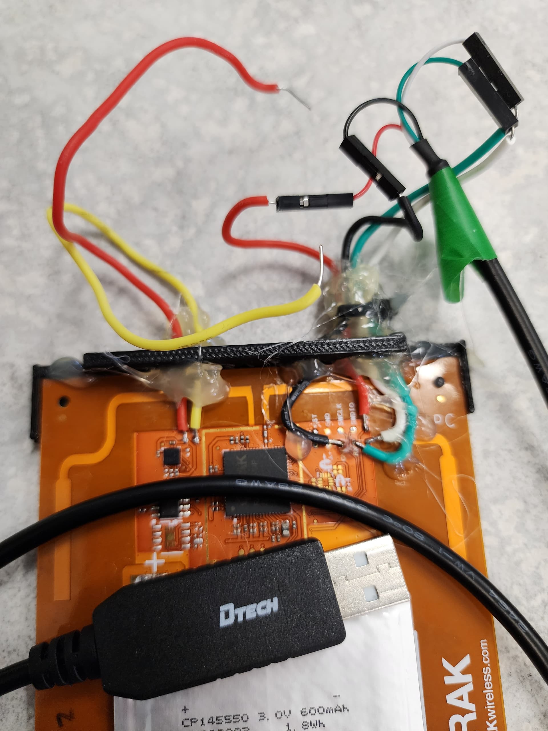
I 3D Printed a base here but not really sure if it is any better than using a ton of Hot Glue to hold the wires in place after the pins have been soldered.
Not pretty but it works:
Anyone got anything to add, should I disconnect the battery?
I can be found here on LinkedIn
Update I did take off the battery.
2nd update. I am back to using another mcu to provide 3.3 Volts to power the board. Strangely USB 5V works fine, but the datasheets seem to think 3.3 volts is what should be used.
Hi @jerteach ,
I’ll let you know once I confirmed with our hardware engineer about the testpoint/pads 1-7.
As for the accelerometer, this library should work fine with RAK2270 - GitHub - sparkfun/SparkFun_LIS3DH_Arduino_Library: LIS3DH Arduino Libs
@carlrowan Awesome, yes the Sparkfun LIS3DH examples work great on the RAK2270 Sticker Tracker easy to load the fullExample and get x,y,z every second.
If you can get from the techs:
Pads 1-7
How to reset (I assume RST to ground)
How to put into boot mode ( I assume Boot0 to ground twice)
Is 5V input VCC from USB ok to use? Much easier than connecting 3.3 V
I am presently checking out CayenneLPP. I am not sure if the data is getting sent properly.
Ok. I am learning a ton about RAK AT commands.
Note: ? is for help
= set (be very careful)
=? get or show the value
AT? is very useful all the commands
ATE Description: AT Command Echo
ATZ Description: MCU Reset
AT+BOOT Description: Bootloader mode
AT+RUN will reset from bootloader mode. (similar to AT+RESET)
AT+DEVEUI=? Description: Device EUI
AT+APPEUI=? Description: Application identifier
AT+APPKEY=? Description: Application Key
AT+JOIN Description: Join LoRaWAN Network (wait a few seconds after the OK. )
AT+NJM=? Description: Network Join Mode (0 = ABP, 1 = OTAA)|
AT+NJS=? Description: LoRa Network Join status(0 = not joined, 1 = joined)|
AT+RECV=? Description: Last received data in hex mode (not working for me)
AT+SEND=12:112233   Send data in port: hex format (not working for me)

AT+CLASS=? Description: LoRa Class A B or C

AT+TXP=?: transmitting power (0 = highest TX power, 14 = lowest TX power) lowest is different

AT+RSSI=?  Gives the RSSI strength of the last connection

AT+ARSSI=? Description: Inquire all channel RSSI

AT+MASK=? Description: Set the channel mask, close or open the channel


AT+BAND=?	Description: Active region
(0 = EU433, 1 = CN470, 2 = RU864, 3 = IN865, 4 = EU868,
5 = US915, 6 = AU915, 7 = KR920, 8 = AS923-1, 9 = AS923-2, 10 = AS923-3, 11 = AS923-4, 12 = LA915)


There are a ton more AT commands. Does anyone else know about any that are really useful.

The P2P AT commands also look interesting.

AT+NWM=? Description: LoRa network work mode[0:Point-to-point, 1:LoRaWAN].Hi Jeremy,
Thaks Again @carlrowan
That explains a lot.and the RAK AT commands are so good I don’t think I have to go down that path again. By the way if I was to try programming the LoRa module like I have done with he Arduino PortentaH7 with LoRa vision shield using GitHub - GrumpyOldPizza/ArduinoCore-stm32l0: Arduino Core for STM32L0
my code is here but would probably need a lot of changes to get pure LoRa working on the RAK2270 sticker tracker.
As I said the RAK AT commands are very powerful so presently I would have no reason to code the module.
That does bring up one question. How on the board do I force typical BOOT mode, not the STM32 boot?
Any suggestions? I know the AT command
AT+BOOT should work and AT+RUN should remove it but from a hardware point of view do you have suggestions.
Finally I got CayenneLPP fake data sent to Helium and then to Adafruit.io
Took a ridiculous amount of time. Not really sure why.
My Github for code is here
We have pin that forces boot mode before but this causes issues so we remove it.
There is no physical way to do it at the moment.
Besides, uploading of new firmware is done via UART so if there is be a software doing the uploading of new firmware, the software needs to issue an AT+BOOT first.
I uploaded now the file for testpoints. You can check it together with test testpoints label in the datasheet.
No Problem. I find your software on the Arduino IDE is fairly good at forcing boot mode. Also the AT command AT+BOOT makes it slightly faster.
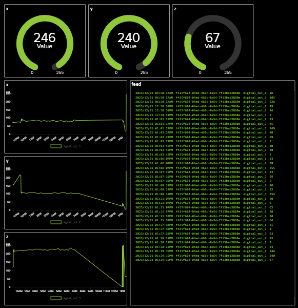
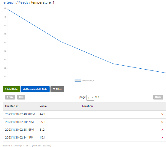
@carlrowan that pin mapping is super useful I will have a new image with pins soon. I am doing well with the accelerometer. Here is an adafruit.io dashboard showing the accelerometer setting converted to 0-255 bytes where 255 would be about 4 G’s. I am very pleased this is working.
…
Really important for people to realize that for me at least this 11 byte AT command works but this 12 byte AT command does not work, and doing an AT+LPSEND is actually sending a few packets so it makes things more complex
AT+SEND=5:112233445566778899AABB These 11 bytes send easily
AT+SEND=5:112233445566778899AABBCC These 12 bytes do not send
but
AT+LPSEND=5:0:112233445566778899AABBCC Sends as 2 or more packets which does seem to confuse Helium and CayenneLPP
Just thought I should mention that.
Note: These commands are used in code as
api.lorarwan.send() or api.lorawan.lpsend()
LoRaQWan and Helium have data limits which is fine for a working product but is horrible for testing. I think the next step is to mess around with both Machine Learning and P2P. If anyone has opinions on the best P2P AT commands please post them.
I have done some p2p work with the Arduino portentaH7 so I am curious if RAK has done any MESH style P2P LoRa connectivity?
What is your region and what is the datarate.
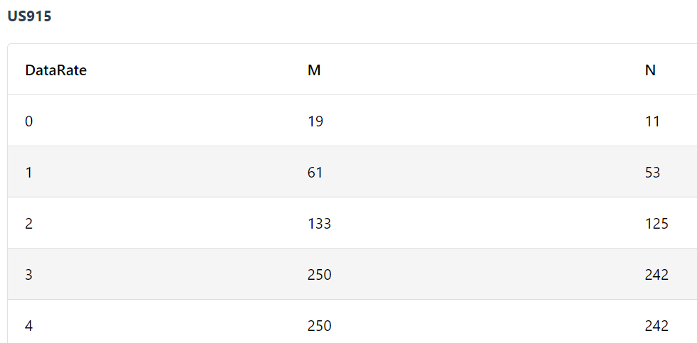
E.g. in US915 at DR0 your payload is limited to 11 bytes.
Max payload per datarate and region
lpsend works only with RAK Edge gateways like the RAK7268 and the internal network server.
Thanks @beegee. Yes, for US915 the chart is
The chart is 11 bytes at the default Datarate. I could do some testing with changing the datarate but my bigger problem is that my machine leaning library here and EdgeImpulse’s ML libraries do not run on the device. For both I am getting an error about the size of the ROM.
Possibly the standard ML program is trying to save data into the wrong location. Anyone know the amount of ROM and flash in the RAK2270 Sticker Tracker, compared to say a XIAO SAMD (32KB SRAM, 256KB Flash ) or Arduino Nano33BleSense (256 KB SRAM, 1MB flash)?
From RAK3172 ROM overflowed - #2 by beegee
looks like it is 250kb flash
RAK3172 evaluation board which is similar
ARM Cortex-M4 32-bit
64 kbytes RAM
256 kbytes flash memory with ECC
Looks like anything that runs on the XIAO SAMD board should run on the RAK2270. I will do a bit more testing.
Side note: Is the battery on the sticker tracker’s rechargeable? If so, does anyone know the typical charge rate, current and voltage for them?
@beegee It looks like the RUI firmware takes up a bit of space. I tried the simplest machine learning code the sine wave and it ran on the XIAO SAMD but was 76K short for the RAK2270 sticker tracker.
Too bad. Without ML ability I will probably have to find something else.
Here is the error message. It looks like it was simply out of memory.
.../.././arduino_build_454572/SineExample.ino.elf section `.text' will not fit in region `ROM'
 region `ROM' overflowed by 76216 bytes
collect2: error: ld returned 1 exit status
Using library RocksettaTinyML-master at version 0.0.2 in folder:..Arduino/libraries/RocksettaTinyML-master
exit status 1
Error compiling for board WisDuo RAK3172 Evaluation Board.
Hi @jerteach ,
The battery of RAK2270 is non-rechargeable. It’s Li-MnO2 voltage with voltage level that will stay around 3V in most of its useful life. Capacity is 600mAh. Specific PN is CP145550.
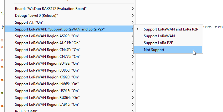
With regards to memory, RUI3 surely occupies memory space with all the features it squeeze on the chip (AT command, API for LoRaWAN/LoRa, Arduino lib support, encryption, etc.)
You might still be able to squeeze if you disable some functions which is supported now by the latest RUI3 firmware. You can even turn off both LoRaWAN/LoRa functions (but might not make sense since it is a LoRa module).