I have been experimenting with the RAK3172 breakout board, and I have been having issues connecting with the UART2 when trying to program using STM32Cube Programmer. I have been able to connect with STLINK V2 by connecting the VDD with Boot0, but I have no luck with UART2. I get the following error when I attempt to do so, then it disconnects. Any help would be greatly appreciated since I would like this to be the main way to program.
16:08:39 : Serial Port COM4 is successfully opened.
  16:08:39 : Port configuration: parity = none, baudrate = 9600, data-bit = 8,                     stop-bit = 1.0, flow-control = off
  16:08:39 : Activating device: OK
  16:08:39 : Response received from device: NACK
  16:08:39 : Error: GETID command not acknowledged!
  16:08:39 : Reemission of GetID command
  16:08:39 : Response received from device: NACK
  16:08:39 : Error: GETID command not acknowledged!
  16:08:39 : Reemission of GetID command
  16:08:39 : Response received from device: NACK
  16:08:39 : Error: GETID command not acknowledged!
  16:08:39 : Chip ID: 0x0
I have an official STLINK V2 but I am not sure why you are using UART instead of SWD pins.
Btw, not all STLINK V2 has UART functionality like the one I have.
If you want UART and not SWD connection, can you try to use a USB-UART converter if you have one then try again? Don’t forget to reset first the device (connect reset pin to ground momentarily) before clicking Connect.
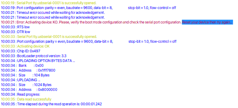
  11:02:46 : Serial Port cu.usbmodem14602 is successfully opened.
  11:02:46 : Port configuration: parity = odd, baudrate = 115200, data-bit = 8,                     stop-bit = 1.0, flow-control = off
  11:02:48 : Timeout error occured while waiting for acknowledgement.
  11:02:48 : Activating device: OK
  11:02:48 : Chipoff ID: 0x497
  11:02:48 : Response received from device: NACK
  11:02:48 : Error: GET command not acknowledged!
  11:02:48 : Reemission of Get command
  11:02:48 : Response received from device: NACK
  11:02:48 : Error: GET command not acknowledged!
  11:02:48 : Reemission of Get command
  11:02:48 : Response received from device: NACK
  11:02:48 : Error: GET command not acknowledged!
Can you try to setup the UART setting to Even parity and baudrate at 9600 so we have the same configuration? I am not sure if this can fix it but that’s the only difference we have.
Also, dont forget to reset (short reset pin to ground momentarily) when you power up the board while Boot0 connected to VDD. This will ensure that you’re device is in UART bootloarde mode.
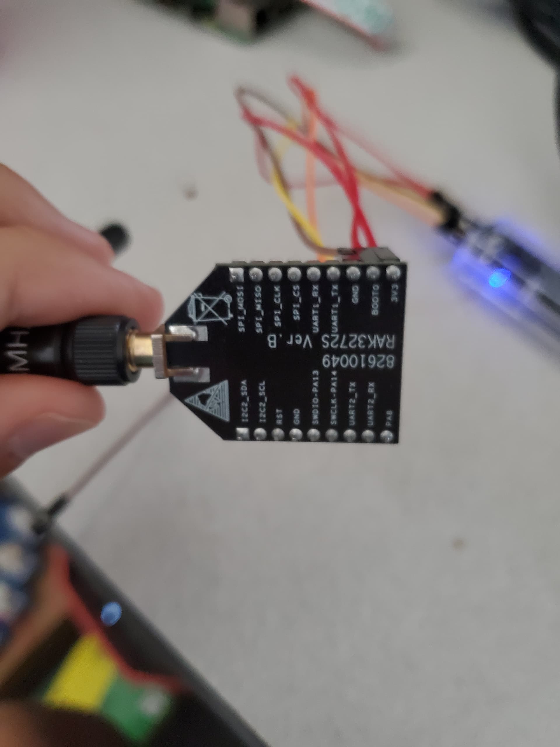
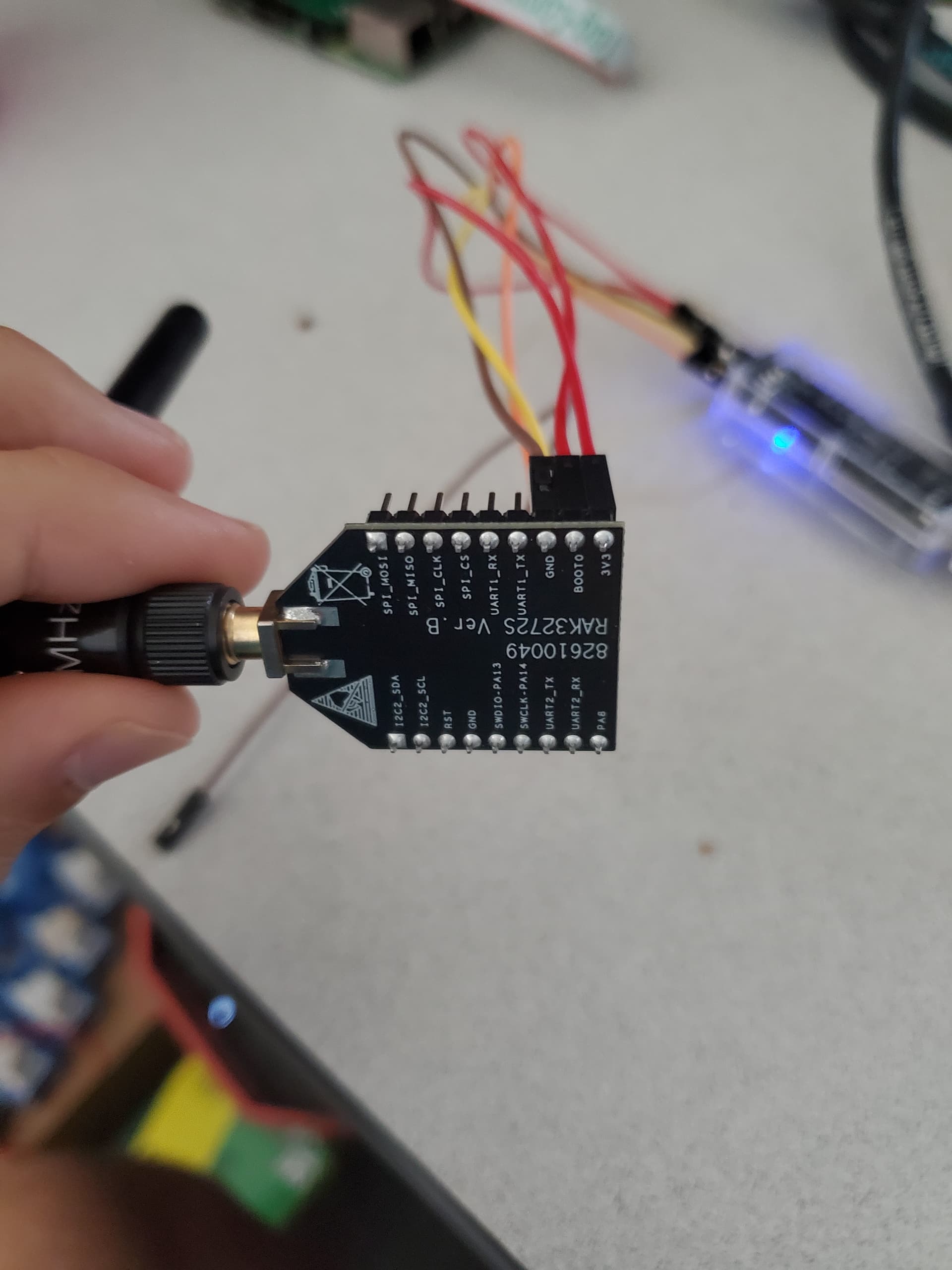
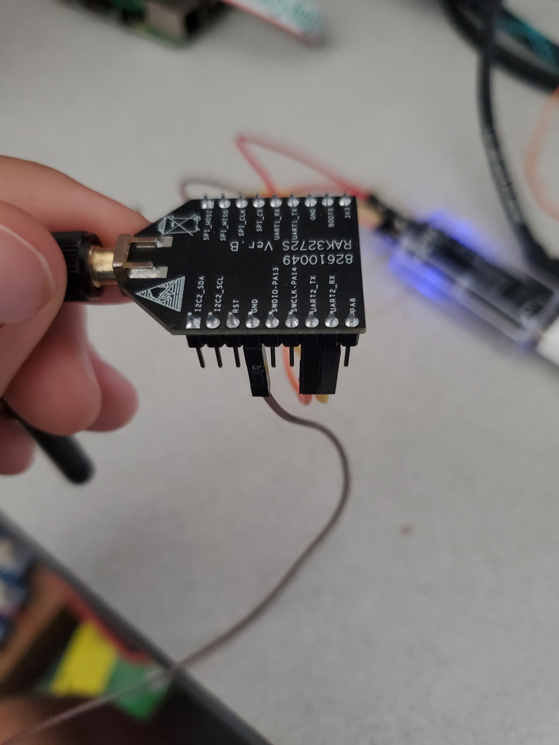
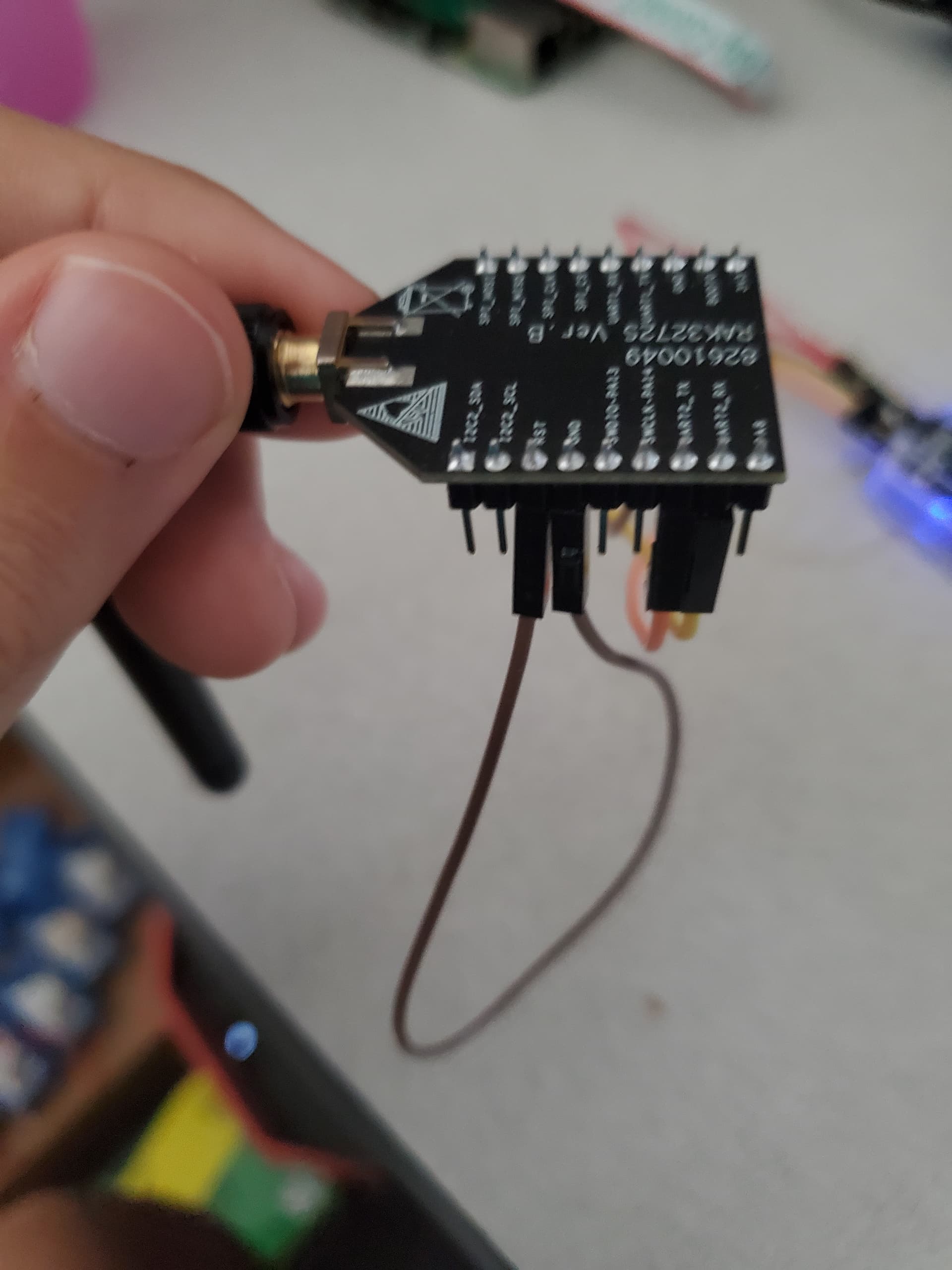
This is the setup that I currently have. Three notes:
I soldered an extra pin to VDD (3.3V), so there are two VDDs for boot0 and VDD pin.
the ground is going into reset from the device, I only do this for a couple of seconds before taking off and attempting to connect to the device.
If I don’t have anything go into boot0 or reset, I get UART output and can enter AT commands. The AT command AT? lists all the possible AT commands for me
Using the RAK3172 breakout board, I did the following:
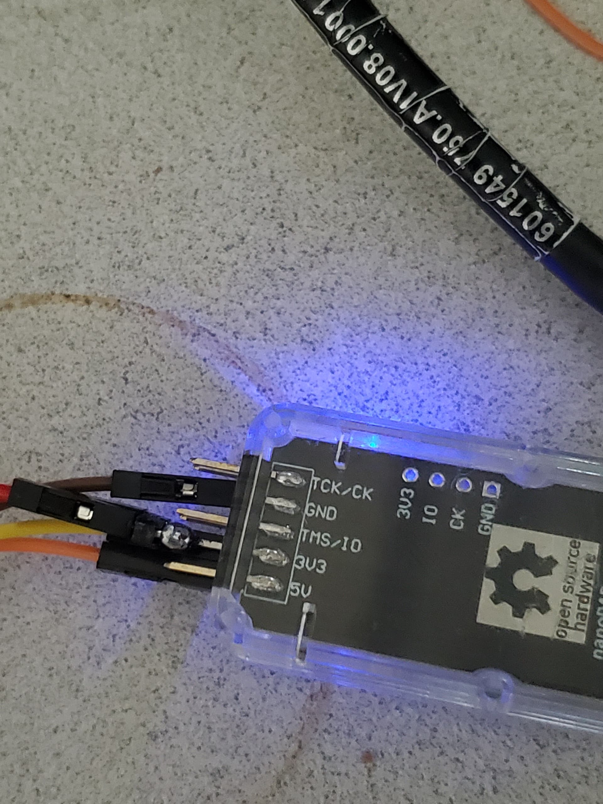
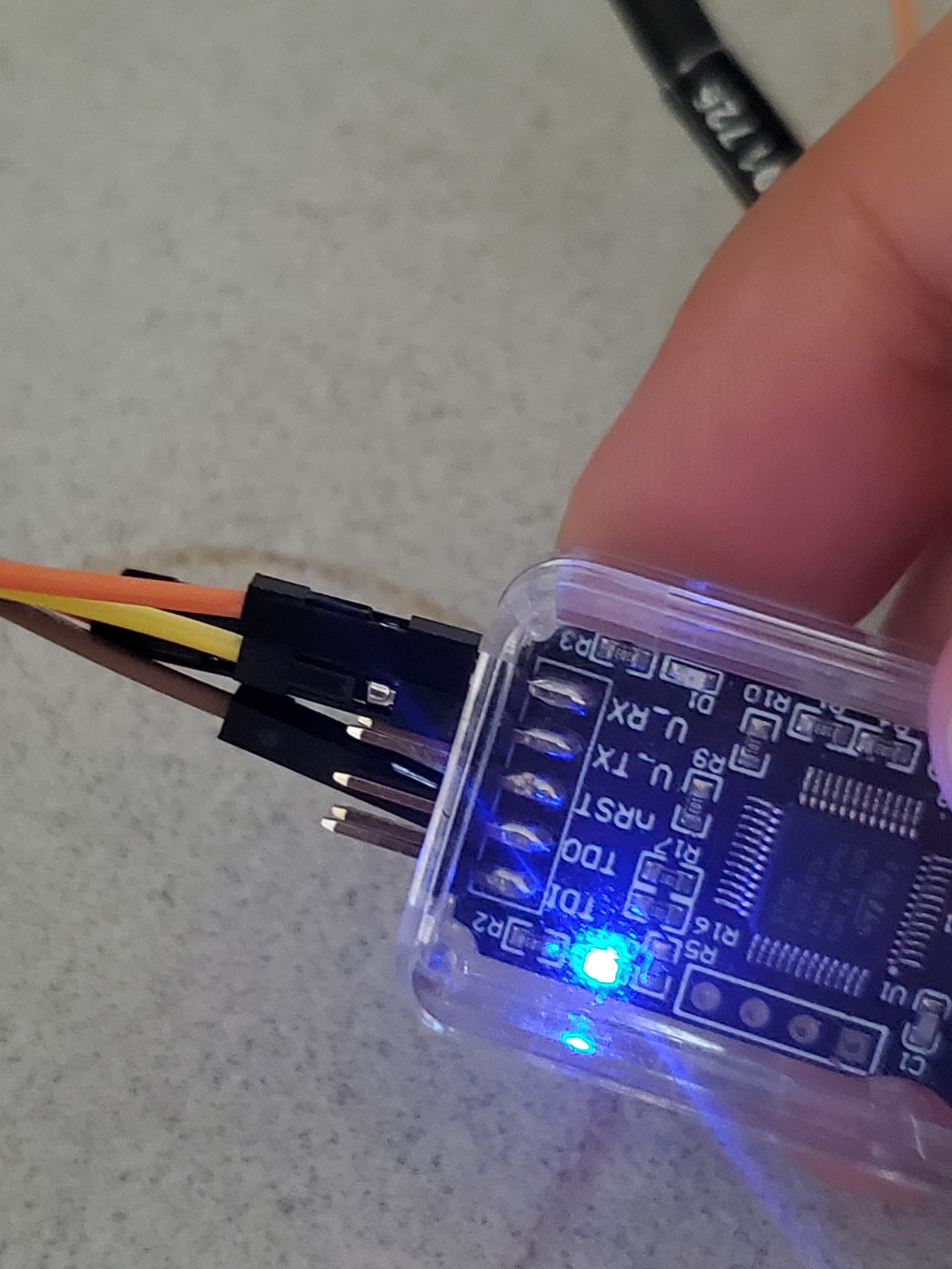
Connect USB to UART adapter with VDD,BOOT0 to VDD,GND, TX and RX to proper pins on board.
Set on UART to COM4, 9600 BAUD rate, Parity=Even
Set the correct COM PORT which in this case is COM4 or whichever window equivalent (tried on both)
Connect GND pin on board to RST pin on board(wait 5 seconds), detach GND from RST (like you mentioned).
Try to connect on STM32CubeProgrammer (V2.8), It tells me no ACK. I get a timeout.
There isn’t any problem with UART because I can disconnect VDD from Boot0 on board and VDD on board, then attach just VDD again(power cycle). Where afterwards I can enter any AT command I want and it works using the RAK serial port tool. So am I missing something obvious? I also included my pin setup below.
All your steps are correct. I can’t find anything wrong. Hmm. Will there be a chance that you can try to a different PC/laptop with STM32CubeProgrammer installed? Also, do you have other USB-UART converter there aside from RAKDAP1? Can you try to uninstall then reinstall the STM32CubeProgrammer? All the hardware step is done correctly so I am not looking on other possible reasons.
Could it possibly be the custom bootloader? The firmware on the two devices I got appears to be here: RAK3172 WisDuo LPWAN Module Datasheet | RAKwireless Documentation Center. I used STLINK to flash the hex file (which includes the bootloader) at address 0, and it looks to be the exact version that came with these boards. Flashing the devices using the RAK firmware Upgrade Tool works fine, and doesn’t require Boot0 to be connect to VDD. I suspect this is the reason why it doesn’t work. I have no access to any other bootloader other than this one. Would another bootloader I could use to flash these with UART? If so, which one and where would I find it?
Hmm. The RAK3172 has custom bootloader when you received it so that it can work with the RAK DFU Tool. But shorting the Boot0 pin to VDD overrides that and uses the chip level UART bootloader. That bootloader is from STMicroelectronics itself.
Whenever you upload a custom .hex or .bin, the original bootloader for RAK will be overwritten by your new FW unless you intentional skip the memory space used by our bootloader.
It is really strange that your STM32CubeProgrammer is not working in UART mode. The only got issues doing this if my jumper wires are not good or if I didn’t reset the module upon power-on with Boot0 pin shorted to VDD.
That’s why to isolate things, I suggest you try a different module (if you have), different PC, etc. In my case, having a laptop with macOS and a desktop with Windows sometimes help me figure out certain issues.
I have already tried three different computers (two windows, one macbook) with the same result on two different breakout boards. All the wires seem to work. The only thing I haven’t confirmed which I will do is if the device is actually resetting if GND is connected to RST on the board.
Are you testing these on RAK3172 breakout boards? My next step is to use a potentially different UART to USB adapter. Also, which STLink with UART are you using to do your test on? It would help me to debug this as a potential issue.
I have two RAK3272 boards and I confirmed that the UART bootloader on STM32CubeProgrammer works by using USB-UART converter of Silabs’ CP2102 and FTDI’s FT232RL. I have no success using RAKDAP1 just like you experience both.
The UART pins of the RAKDAP1 seems to have conflict with the STM32CubeProgrammer. I usually use my RAKDAP1 for pyocd uploading and not as USB-UART converter. The RAKDAP1 is ok though if you will just send AT Commands.
This is something to look at but could be related to Debug Access Port (DAP) UART implementation.
It will help if you can try again using a different USB-UART converter board.