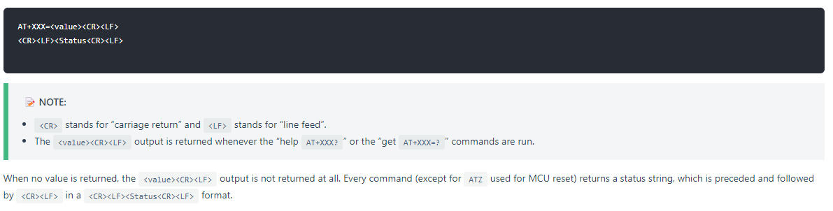
I am new to LPWAN technology, but I have read and Learned about it and I bought Rak 3172-e evaluation board. Now, I want to connect this evaluation board to external microcontroller (Cypress Microcontroller), and send the AT commands through UART to rak 3172 module. Is there, any reference mannual availabe for, how to connect RAK3172-E with external micro-controller, and comminicate through UART? OR, if there is no refernece mannual, How the hardware connection should be?
Below, I am attaching the code, which I tried to implement through Psoc Creater IDE for Cypress Microcontroller:
#include "project.h"
#include <stdio.h>
#include <stdbool.h>
#include <string.h>

#define UART_BUFFER_SIZE 256
char uartBuffer[UART_BUFFER_SIZE];

// Function to send an AT command over UART
void sendATCommand(const char* command)
{
    UART_PutString(command);
    UART_PutString("\r\n");
}

// Function to receive data from UART
void receiveUARTData()
{
    uint8_t byte;
    uint16_t index = 0;

    while (UART_GetRxBufferSize() > 0 && index < UART_BUFFER_SIZE - 1)
    {
        byte = UART_GetByte();
        uartBuffer[index++] = (char)byte;
    }

    uartBuffer[index] = '\0'; // Null-terminate the received data
}

// Function to check if a specific response is received
bool checkResponse(const char* response)
{
    return (strstr(uartBuffer, response) != NULL);
}

int main(void)
{
    __enable_irq(); // Enable global interrupts

    CyGlobalIntEnable; /* Enable global interrupts. */

    UART_Start();

    // Send AT command
    sendATCommand("AT");

    while (1)
    {
        if (UART_GetRxBufferSize() > 0)
        {
            receiveUARTData();

            // Check if "OK" response is received
            if (checkResponse("OK"))
            {
                // Handle "OK" response
                // Do something here when "OK" is received
                Pin_1_Write(1u);
                CyDelay(1000);
                Pin_1_Write(0u);
                break; // Exit the loop and move to the next step or state
            }
        }
        CyDelay(100);
    }

    // Continue with the next steps or states

    for (;;)
    {
        // Implement your main program logic here
    }
}


/* [] END OF FILE */
The AT commands for RAK3172 is based on RUI3 AT Commands. You can check the documentation here.
I am not familiar with Cypress and its Psoc IDE.
However, in your code, I do not see what baudrate you use. UART_Start() codes is not shown. Maybe you can double check if it is 115200. Also on checkResponse(), OK might not be enough and terminations must be included. I am not certain on that but something you can check as well. You have to check the command on its actual format. Some commands has multiple replies other than OK.
Hi,
Thank you so much for the feedback @carlrowan.
In Psoc IDE, I can directely set Baudrate with the API. So, I have already set it to 115200. I wanted to known, the hardaware connection between Cypress Micro-controller and RAK3172-e evaluation board. Uptil now, I have connected, Tx of M/C to Rx (PB7) of Rak3172 evaluation board and Rx of M/C to Tx(PB6) of Rak3172evaluation board. I am giving 5V from external power supply to rak3172 evaluation board VDD Pin and GND to GND. Anyother connection (Like BOOT0 Pin) I have to do, In order to start Rak3172evaluation board.
So, I have to directly upload this firmware from Arduino IDE to evaluation board through USB and after that it will change to UART 1, Correct? Or, I have to write in Psoc IDE with my UART code?
The way I understand it, your Cypress MCU is connected to UART1 and trying to send AT commands.
Since UAR1 is not useable for AT commands by default, you have to upload the code I shared above to the RAK3172 module in your RAK3172 Evaluation Board so that UART1 will be enabled to accept AT command. Of course you need to add RAK3172 in the board selections of your Arduino IDE. You can follow this guide how to add RAK3172 in your Arduino IDE.
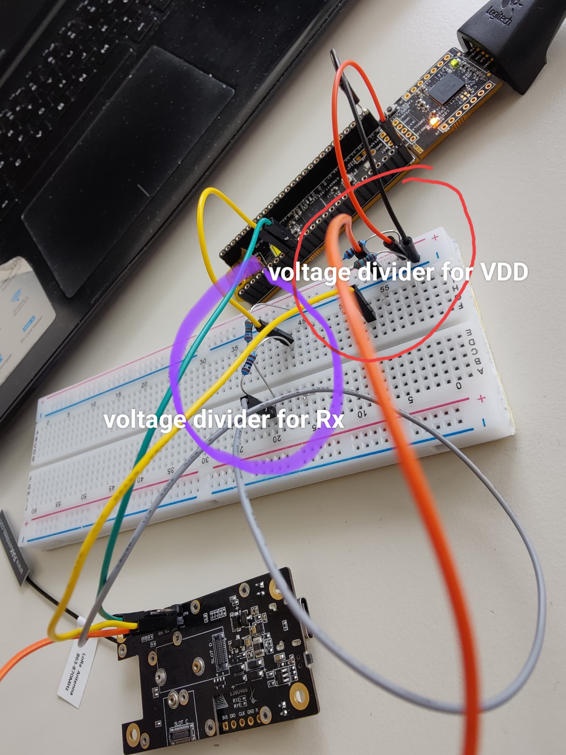
With regards to @beegee comment, if the UART lines of Cypress is 5V. You can connect RAK3172 TX directly to RX of Cypress MCU. But the RAK3172 RX needs a voltage level shifter. It can be a simple voltage divider but you can also use commonly used voltage level shifter boards.
You also need to connect the ground.
But for the VDD, you cannot use 5V directly to RAK3172. You have to step it down to 3.3v via voltage regulator. Or use an external source like battery to your RAK3172-Eval Board. Then just connect the gnd of both boards.
I tried with this connection also, connecting Tx with Voltage divider and from voltage divider to Rx of Rak3172. Also, I downloaded the firmware, in Rak evaluation board. But, it is still not working. Below, I am attaching the photo for hardware connection and also, C code for UART communication for your reference.
Code:
#include "project.h"
#include <stdio.h>
#include <stdbool.h>
#include <string.h>

#define UART_BUFFER_SIZE 256
char uartBuffer[UART_BUFFER_SIZE];

// Function to send an AT command over UART
void sendATCommand(const char* command)
{
    UART_PutString(command);
    UART_PutString("\r\n");
}

// Function to receive data from UART
void receiveUARTData()
{
    uint8_t byte;
    uint16_t index = 0;

    while (UART_GetRxBufferSize() > 0 && index < UART_BUFFER_SIZE - 1)
    {
        byte = UART_GetByte();
        uartBuffer[index++] = (char)byte;
    }

    uartBuffer[index] = '\0'; // Null-terminate the received data
}

// Function to check if a specific response is received
bool checkResponse(const char* response)
{
    return (strstr(uartBuffer, response) != NULL);
}

// Function to wait for a specific response with the specified timeout
bool waitForResponse(const char* response, uint32_t timeout)
{
    uint32_t startTime = CySysTickGetValue();

    while (true)
    {
        if (UART_GetRxBufferSize() > 0)
        {
            receiveUARTData();

            if (strstr(uartBuffer, response))
            {
                return true;
            }
        }

        if ((CySysTickGetValue() - startTime) > timeout)
        {
            return false; // Timeout occurred
        }
    }
}

int main(void)
{
    __enable_irq(); // Enable global interrupts

    CyGlobalIntEnable; /* Enable global interrupts. */

    UART_Start();

    // Send AT command
    sendATCommand("AT+ATM");

    while (1)
    {
        if (waitForResponse("\r\nOK\r\n", 1000))
        {
            // Handle "OK" response
            // Do something here when "OK" is received
            Pin_1_Write(1u);
            break; // Exit the loop and move to the next step or state
        }
        else
        {
            // Handle timeout
            // Do something here when the response times out
            Pin_1_Write(0u);
            break; // Exit the loop and move to error handling or next step
        }
    }
}
If I am in your situation, I will try to check first if the TX and RX of UART1 is working by using an external USB-Serial converter. This is the same on how I will test the Cypress chip. I can send some UART data to it or maybe emulate first the behavior of the RAK3172 via Serial Terminal. Then if I am confident that both sides are working fine, then I can connect it together. Another thing you can do is check the UART lines with Logic Analyzer with UART decoding functionality so you can see what UART data are being thrown on both side.
I just noticed you used voltage divider for VDD. You shouldn’t do that approach because you will have an uncontrolled voltage drop (in theory could be possible if the resistors a very low). You must use an voltage regulator on 5V.
For this test, you can probably just use USB supply for the RAK3172 Evaluation board and just connect GNDs of both boards.
I tried using USB-Serial converter and also, with logic analyzer to analyze the bits, but it did’nt work, So, I think Lora module is damaged, because, when I tried with another RAK3172-E Module, with USB-Serial converter, using UART1, it worked properly, I can see the response in the terminal. Now, I am trying with Cypress Micro-controller. Regarding UART communication Code, which I have written, Is it Correct?
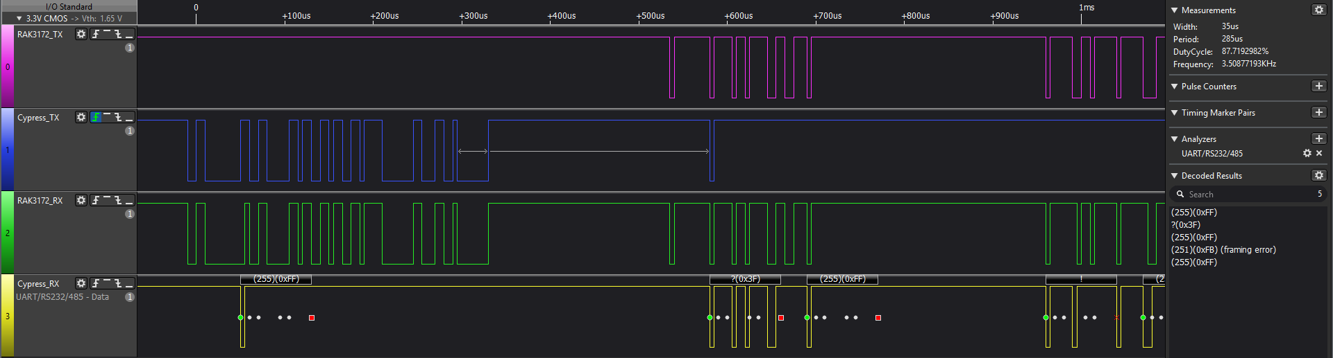
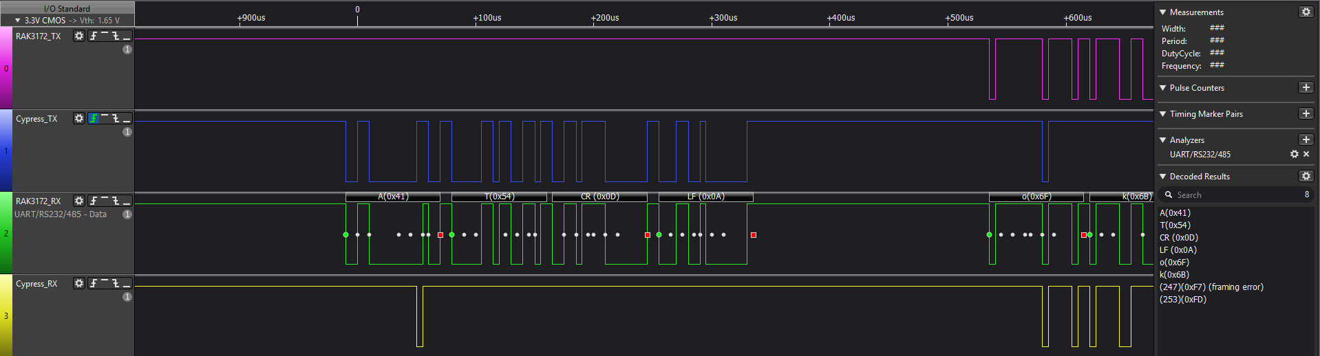
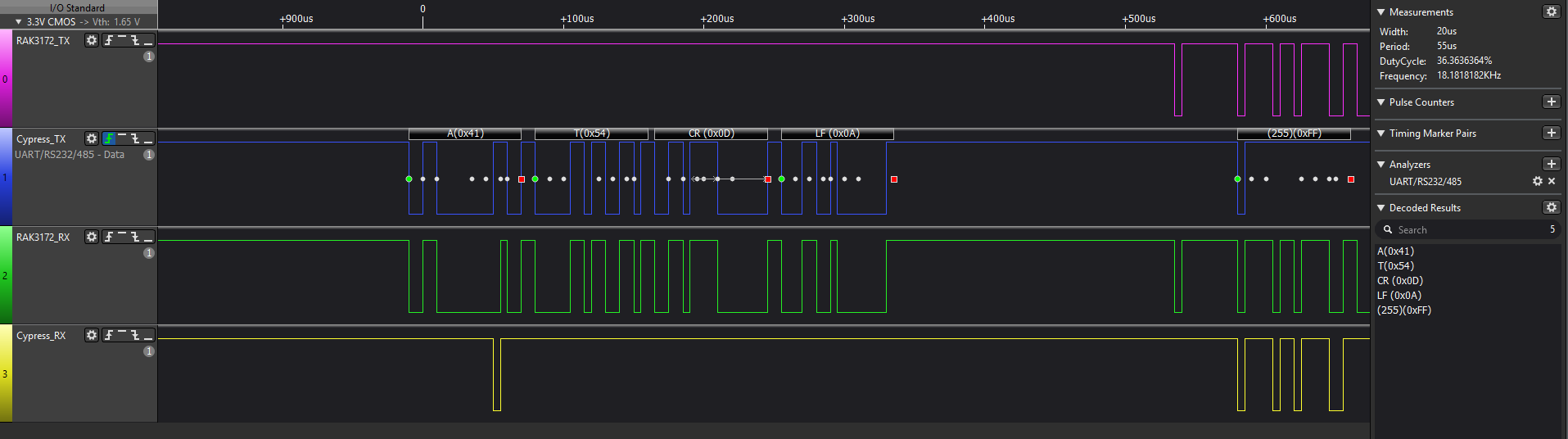
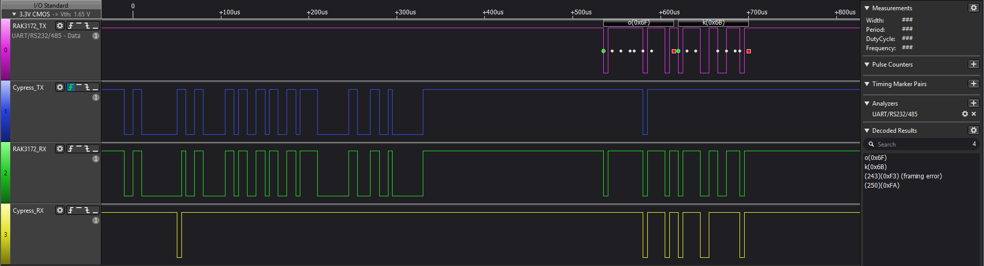
I have connected, RAK3172 with Cypress, and I am trying to send AT command, and checking the responce, RAK is transmiting OK or not. I checked with Logic analyser, below I am attaching the Screenshots, Can you help me, Why on recieveing side of Cypress, OK is not recieved, How can I edit my code?
I cannot help you much on the code. But on the logic analayzer, it is strange that you see both ok on TX and RX line of RAK3172. Also the RX on Cypress side has missing pulses. It might be a good idea to get a oscilloscope and check the signal levels. If there is skewing issues, you can try to lower the baud rate or use lower resistance on your voltage divider.