We are trying to use ADC with 12 Bit resolution and reference voltage 3.3V.
Here we have connected R1=1 MOhm and R2=1.5 MOhm, voltage divider to Pin Number 32 (WB_A0).
Below are our observation(s)
a. analogRead() returns 1863 (i.e. adc_value) reading
b. After converting 1863 to voltage gives as 2.5 volts using below formula
V = (Vref * (adc_value) / max_adc_reading) / (R2/(R1 + R2))
V = (3.3 * (adc_value) / max) / (1.5/(1 + 1.5)) = 2.50V
Can you please help me to understand at what point I am going wrong as I am expecting voltage reading to be 3.3V as I have given 3.3V voltage divider?
Thanks for your reply.
However can you please help us to understand why we are seeing 2.50V when it should come as 3.3V.
Do we need to change any hardware or software?
When you say you are seeing 2.5V, is it on the battery get API or your manual ADC reading? If on the latter, I have to check first with the team the internal implementation of WB_A0. I’ll get back to you as I got the information.
Please note that earlier we used battery API but it is giving fixed 3.00V reading. So we have moved to manual ADC.
Also I am attaching sample code and output log for your reference.
Output log: ADC pin [19] value = 464, reference = 3.30, max = 1024.00 Voltage1 value = 2.492188 V
Please guide.
Regards,
Dinesh
//Set pin number
uint8_t analogPin = WB_A0;

void setup()
{
  // initialize serial communication at 115200 bits per second
  Serial.begin(115200);
  Serial.println("RAKwireless Arduino Analog Example");
  Serial.println("------------------------------------------------------");

  analogReadResolution(10);
  // udrv_adc_set_resolution(UDRV_ADC_RESOLUTION_10BIT);
  // analogReference(AR_INTERNAL_3_0);
  udrv_adc_set_mode(UDRV_ADC_MODE_3_3);
}

void loop()
{
  float max, ref;

  switch (udrv_adc_get_resolution()) {
      case UDRV_ADC_RESOLUTION_6BIT:
      {
          max = 64.0;
          break;
      }
      case UDRV_ADC_RESOLUTION_8BIT:
      {
          max = 256.0;
          break;
      }
      case UDRV_ADC_RESOLUTION_10BIT:
      default:
      {
          max = 1024.0;
          break;
      }
      case UDRV_ADC_RESOLUTION_12BIT:
      {
          max = 4096.0;
          break;
      }
      case UDRV_ADC_RESOLUTION_14BIT:
      {
          max = 16384.0;
          break;
      }
  }

  switch (udrv_adc_get_mode()) {
      case UDRV_ADC_MODE_DEFAULT:
      default:
      {
          ref = 3.6;
          break;
      }
      case UDRV_ADC_MODE_3_3:
      {
          ref = 3.3;
          break;
      }
      case UDRV_ADC_MODE_3_0:
      {
          ref = 3.0;
          break;
      }
      case UDRV_ADC_MODE_2_4:
      {
          ref = 2.4;
          break;
      }
      case UDRV_ADC_MODE_1_8:
      {
          ref = 1.8;
          break;
      }
      case UDRV_ADC_MODE_1_2:
      {
          ref = 1.2;
          break;
      }
  }
  int adc_value = analogRead(analogPin);
  Serial.printf("ADC pin [%d] value = %d, reference = %.2f, max = %.2f\r\n", analogPin, adc_value, ref, max);
  // This is the formula to get the input voltage of RAK5811:
  Serial.printf("Voltage1 value = %f V\r\n", ref*(((float)adc_value)/max)*(5.0f)/(3.0f));
  Serial.println();
  delay(5000);
}
OK We will take trial accordingly.
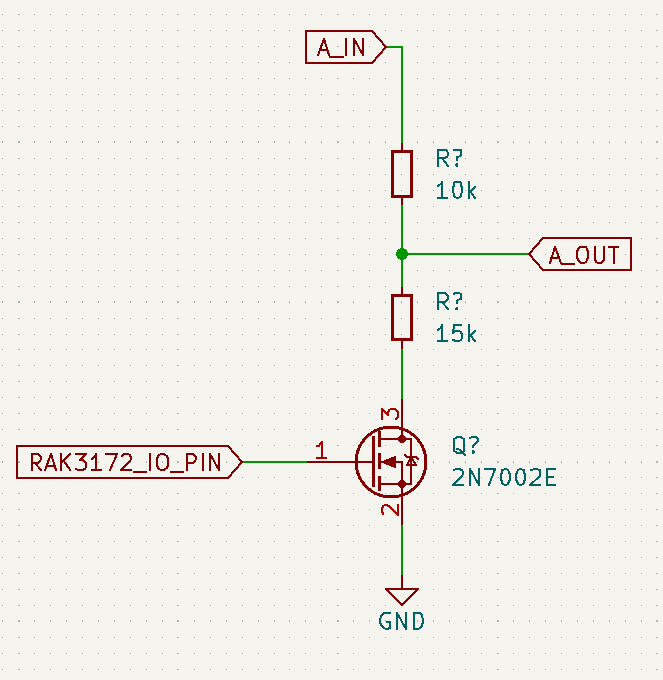
However please note that it will draw 0.132 mA (132 uA) at 3.3V supply voltage which is not acceptable.
If you have any other solution with lesser current consumption say couple of uA the please suggest.
You can use an IO pin to control the mosfet. You have to consider though the very small Rds ON resistance which can be offset by calibration if accuracy in your application is crucial.