Please include the following information, in order for us to help you as effectively as possible.
What product do you wish to discuss? RAK4631, RAK3372, RAK11200, RAK11310, RAK11722?
→ RAK3172.
What firmware are you using? (RUI3 or Arduino BSP or other IDE (e.g. STM32CubeIDE)?
–>Arduino IDE for sending AT commands
What firmware version? Can it be obtained with AT+VER=?
–>AT+VER=RUI_4.2.0_RAK3172-E
Computer OS? (MacOS, Linux, Windows)
–>Windows 10
What Computer OS version?
22H2
How often does the problem happen?
–>always
How can we replicate the problem?
→ some AT commands are not working like AT+BFREQ=? it is saying AT_NO_CLASSB_ENABLE but we set as AT+CLASS=B and it is showing AT+CLASS=B:S0 BUT STILL, AT+BFREQ=? THIS COMMAND IS NOT WORKING and also other few commands also. and we don’t know that is it ok to upgrade the firmware
Provide source code if custom firmware is used or link to example if RAKwireless example code is used.
→ no, we are not using any source code just sending the at commands
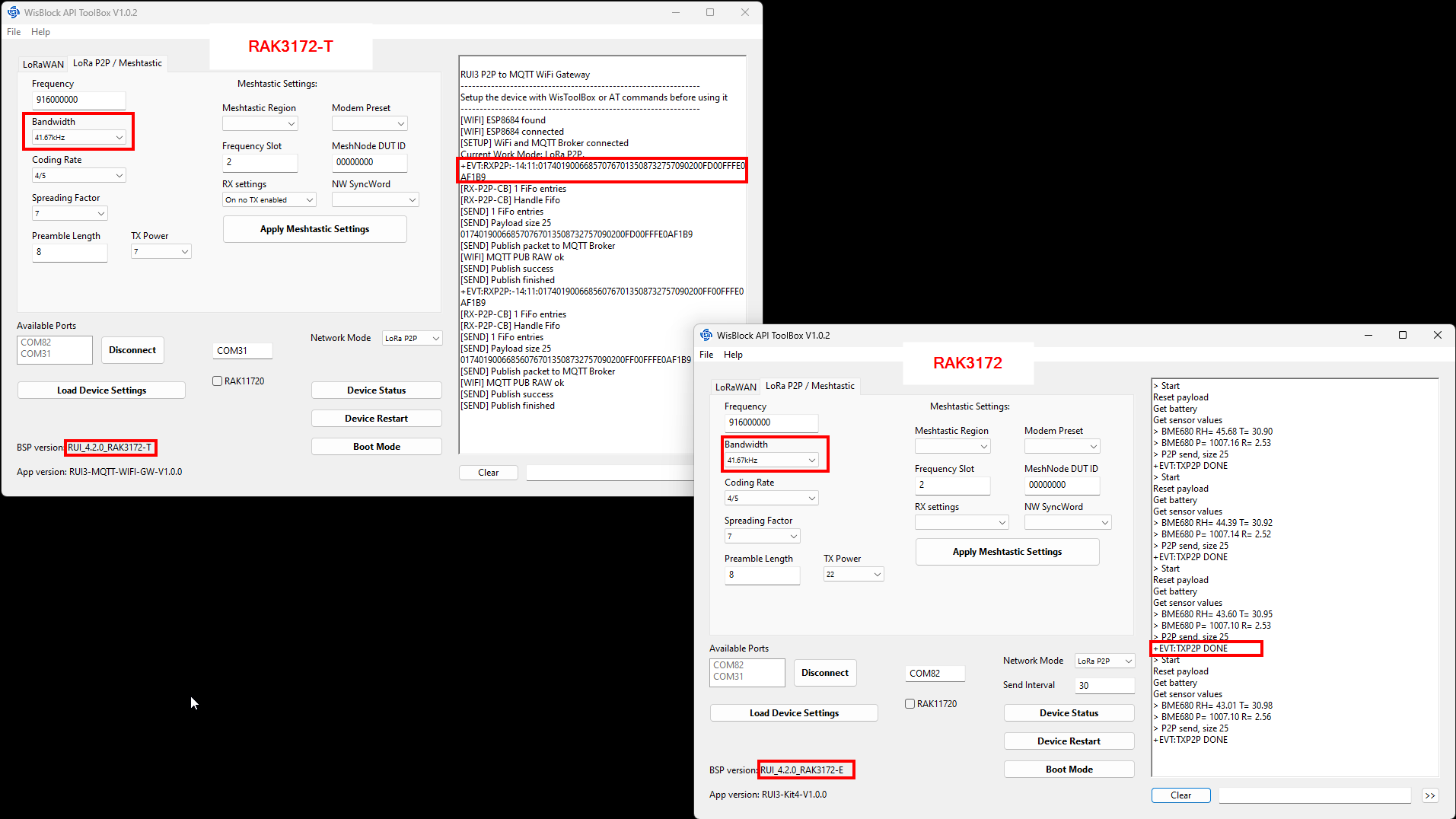
(1) Are you sure you have a RAK3172-T? Because the output of AT+VER suggests that you have either a RAK3172 without TCXO or you have the wrong firmware installed.
If your module is really a RAK3172-T, the correct response would be:
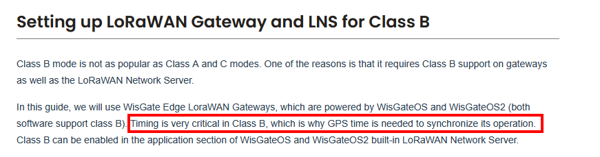
If you are still in AT+CLASS=B:S0 state, you will not be able to check the frequency so nothing is wrong in what you see. You need to send an uplink first with AT+CLASS=B enabled (but actually this first uplink is still in class A until you got the beacon lock state).
You can only make this possible if the LNS supports Class B and your GW has GPS.
To check if you got beacon lock, your AT+CLASS=? will return
Can you please tell me that how to install/update the firmware for RAK3172(T1) step by step and set up.
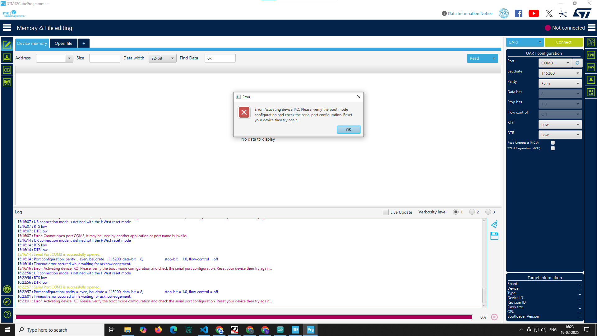
I tried to upload the latest firmware downloaded from website with the help of STM32 Cube Programmer using TTL(UART) connection at that time
16:22:56 : UR connection mode is defined with the HWrst reset mode
16:22:56 : RTS low
16:22:56 : DTR low
16:22:57 : Serial Port COM3 is successfully opened.
16:22:57 : Port configuration: parity = even, baudrate = 115200, data-bit = 8, stop-bit = 1.0, flow-control = off
16:23:01 : Timeout error occurred while waiting for acknowledgement.
16:23:01 : Error: Activating device: KO. Please, verify the boot mode configuration and check the serial port configuration. Reset your device then try again…
this error comes but when I uploaded the code using Arduino ide that time need not required to set RAK3172 in to the boot mode, it automatically goes to boot mode
Please guide me properly.
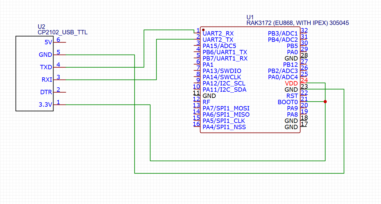
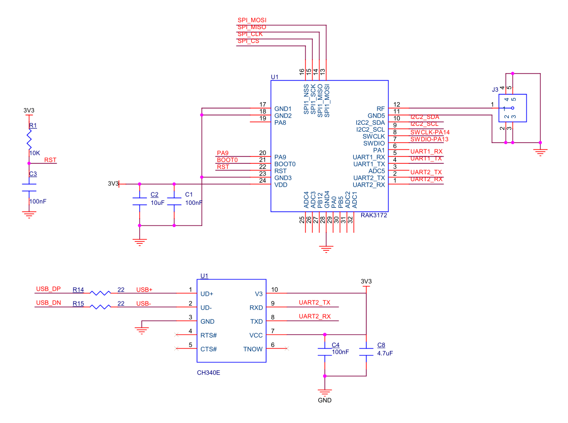
On using STM32CubeProgrammer, you need to use to UART2 and connect BOOT pin to VCC. You have to reset the RAK3172 to enable boot mode of the STM32WL. This is different on the bootloader mode of RUI3. After resetting, click connect on STM32Cubeprogrammer. This should establish the connection.
Some troubleshooting:
Make sure no other terminal software is using that COM port like Arduino IDE.
The jumper wires to your USB-Serial is working ok.
We did this connection, then from https://downloads.rakwireless.com/#LoRa/RAK3172/Firmware/
this website downloaded the latest firmware and uploaded using the stm32 cube programmer, on stm32 cube programmer below message shows after we update the firmware (.bin file - RAK3172-E_latest.bin)
16:53:32 : Time elapsed during download operation: 00:00:24.862
17:01:38 : Opening and parsing file: RAK3172-E_latest.bin
17:01:38 : Memory Programming …
17:01:38 : File : RAK3172-E_latest.bin
17:01:38 : Size : 182.30 KB
17:01:38 : Address : 0x08000000
17:01:38 : Erasing memory corresponding to segment 0:
17:01:38 : Erasing internal memory sectors [0 91]
17:01:40 : Download in Progress:
17:02:03 : File download complete
17:02:03 : Time elapsed during download operation: 00:00:24.940
17:02:03 : Verifying …
17:02:03 : Read progress:
17:02:24 : Download verified successfully
then we removed the boot pin from vcc to ground then pressed the reset button and connected with QCOM_V1.6 to check AT command response but “AT” command is not worked or not sent to the rak board
It looks like the bootloader is erased when you are using the STM32CubeProgrammer.
Use the RAK3172-E_latest_final.hex file instead.
The HEX file includes the bootloader.
In your website for RAK3172-T there is no firmware only Crystal oscillator verification report is available. But for the RAK3172 firmware is available as .hex & .bin file, should we bother about that
In our LORA chip mentioned thing is RAK3172(T1), so we are confused that our model is T1 but at your side there is no firmware available for this device.
And also please tell us should we go with USB to TTL converter for firmware upload or we have to use ST-link for the same.
As mentioned by you we uploaded the the new firmware in the RAK3172-T1 model using our connection diagram, we connected the reset to ground via push button.
After uploading the new firmware should we need to do anything extra from our side? From our side we removed the problem supply
cause now problem is we are not getting AT commands response.
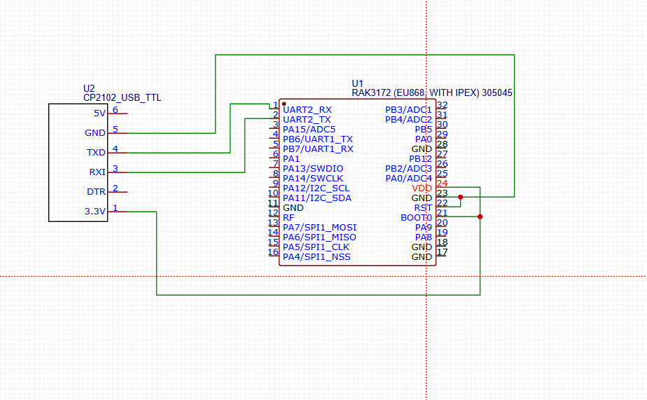
It should be only connected temporary to VDD when you use STM32CubeProgrammer. Otherwise you should leave the pin open. BOOT0 has an internal pull-down resistor to GND.
Yes, you need to release BOOT0 after the firmware update.
Otherwise the RAK3172 will be stuck in STM32 Bootloader mode and not start the application code.
We have encountered the new problem, we changed the bandwidth form 0 to 8 by using AT+BANDWIDTH=8 this at command( AT+BANDWIDTH : get or set P2P Bandwidth(LORA: 0 = 125, 1 = 250, 2 = 500, 3 = 7.8, 4 = 10.4, 5 = 15.63, 6 = 20.83, 7 = 31.25, 8 = 41.67, 9 = 62.5 FSK:4800-467000))
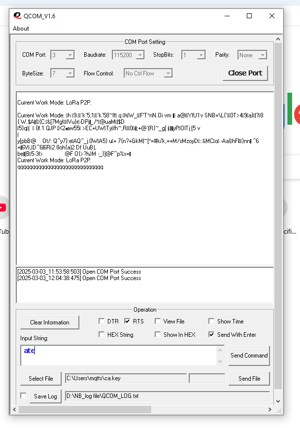
just for checking, it works able to send at commands but after 20 minutes i am sending the at command but there is no response from the RAK372-T device and this are below logs in image
in above images after clicking reset it shows Current Work Mode: LoRa P2P.
fine but if i press reset button again then some garbage value is coming and if i put ATZ command means soft reset then it shows that “q” message and for ATE command also.
Not able to change the “current mode” and “BANDWIDTH”
then i dumped the code for led blinking and guess what it works fine, but for AT commands i am not getting proper response.
After you started the app, connect the device you want to setup/debug.
Then use “Load Device Settings” to get the device info.
You can send AT commands manually to the device through the input box below the debug output.
Other stuff is self explaining, I think.
Is there a way to determine if the RAK3172 chip is in good condition and not short-circuited? We have soldered a new schematic based on our own design; however, when we connect the TTL side to the PC, both TX and RX are constantly HIGH, and the serial terminal displays “AT_COMMAND_NOT_FOUND.”
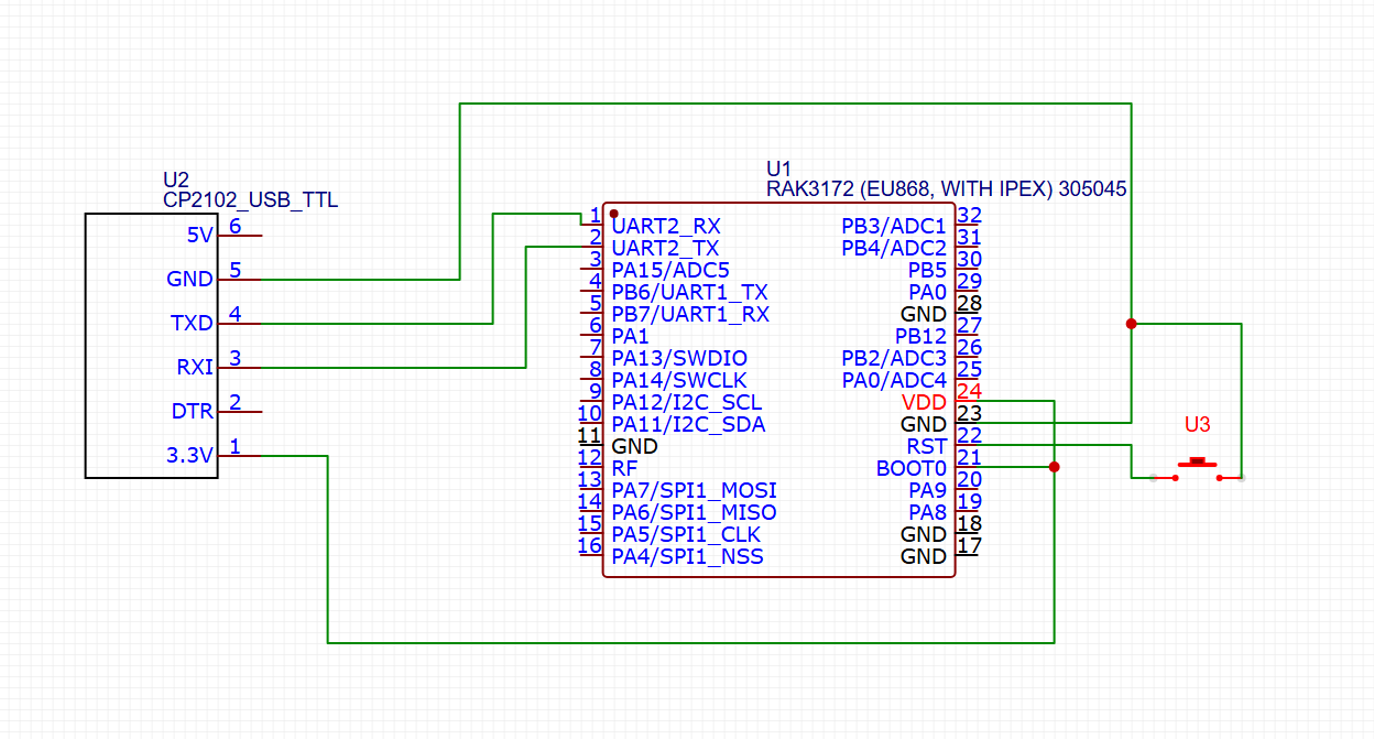
Later, we tested the circuit shown on the RAK website:
Repeating the same post doesn’t help you to get answers.
I deleted the copy.
If the RAK3172 is not booting up on your custom PCB, it can have many reasons.
You have to check everything, from false solder connections, correct supply voltage to erased flash of the MCU