BOM- Aside on the RAK3172LP-SiP, headers and passives. The critical ones are the bead and inductor. Here’s the part number of the bead (BLM15PD121SN1B ) and inductor (LQM21DN150M70L)
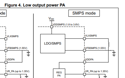
I wonder about the schematics. For Low-Power Mode the ST-Datahsheet tells me to connect VDDPA to VFBSMPS (1.55 Volts):
But the schematic link of the Eval-Board has VDDPA connected to VDD (3.3V)?
This is also what I find on the RAK3172LP-SIP Breakout-Board.
I came accross this issue, because my protos Proto RAK3172LP-SIP draw higher current than expected (ca. 57mA @ 14dBm). Still less, than if Standard RAK3172-SIP is used, but much more than other LoRa modules I knew.
Does the schematic for the RAK3172LP-SIP require VDDPA as 1.55V or 3.V?
Your observation is correct. We are releasing a new Breakout Board for RAK3172LP-SiP with VDDPA going 1.55V (VFBSMPS). We weren’t able to changed the breakout board when we released the RAK3172LP-SiP which is a year later after than the original RAK3172-SiP was launched.