RAK4200 antenna connection and pcb layout

When using the IPEX connector that is on the RAK4200 stamp module, what should be done in regard to RF Pin 12 on the stamp.

Is it ok to have a pad for it to solder to without connection, or should that pad be deleted from the PCB completely?

Secondary question, are there any recommendations in regard to keeping the area below the stamp clear of traces, or adding ground planes etc.

Dear John_NZ,

Can you show your product picture?

I can post photos, but may I ask why?
The present PCB is prototype and I am just preparing another version of the board, so the next one will be different to this one, this is why I am asking about PCB layout considerations for the RAK4200.

I am having trouble with the LoraWAN communication.
I have tried various antennas and have poor performance. One unit is joining on occasion and the other never joins. So I am thinking it may be due to the layout of the PCB is not good for the RF

Do you have a PDF of the RAK4200 EVB PCB layout?

Hi @John_NZ :wave:t2: ,

The RAK4200 EVB is build with two modules. The RAK4200 WisDuo LPWAN Module and RAK5005-O Base Board so there is no single PCB layout because there are two modules.

In general there are no PCB layouts published, only the schematics. You can find both datasheets in the documentation site:

For additional support about your case, please contact our support team using the chat available at the bottom right of the documentation. We’ll happy to assist your case :smile:

Cheers,
Maria H.

Thank you.

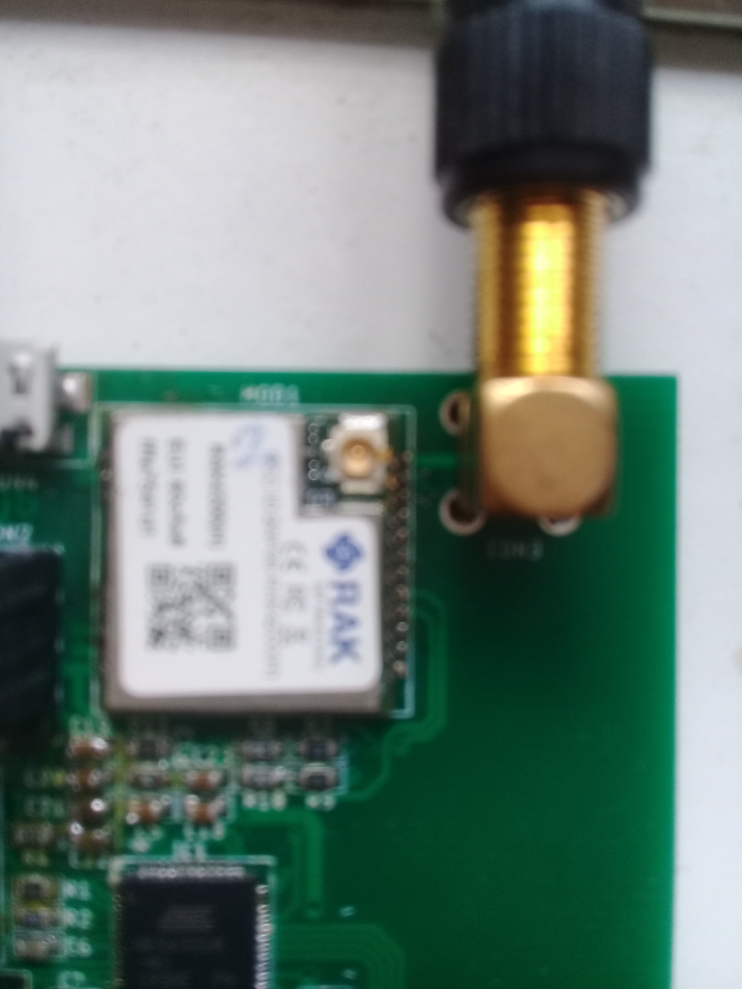
I have added an external IPEX connector to the RF pin on the RAK4200 module as per the recommended layout.
How do I configure the RAK4200 in software to use the external RF pin.
I see in the data sheet that the onboard IPEX is the antenna connection by default, but I can’t find any guidance on making the RAK4200 use the external RF connection.

Cheers,
John

As there is no on-board antenna on the module, there’s nothing to switch off - just don’t use both U.FL connectors at the same time!

The module documentation, schematic & recommended circuit show this - check out the downloads section.

1 Like

Hi, this is the RAK4200 board that I have made.
External whip antenna: 3dbi.
Gateway: RAK7258
EU868MHZ

Why transmit distance is poor, no more than a few tens of meters ?

Please see,
SMA connector is as close as possible to RF (12) PIN,
No matching circuitry.
(Pcb bottom: full ground plane)

Earlier I played with RAK811 for the same external antenna short pcb trace. Tested succesfully as greater than 1 Km.

What happens if you unscrew your antenna and use one plugged in to the U.fL socket?

Can you try the helical one that ships with the module as well as your own antenna.

Hi @nmcc,
yes I would try it, but I haven’t got U.fl to SMA antenna cable adaptor. I will have one and try.
If succesful, Do you advise not to use RAK4200 RF OUT PIN without matching circuit ? Practically, how effects a short 1cm pcb trace at 868Mhz ? RAK811 had no trouble.

Hi @leanofis,

I haven’t had much luck yet with using the RF Out Pin. I have a matching circuit as per the schematic from RAK, but I haven’t worked out the components that I need to use yet.
I have a VNA, I just need to do some setups and some calculations to get the match correct.

@nmcc thank you,
Using RF PIN and a second pcb connector for antenna was a good static mounting option in my design. I have no more RF knowledge/instruments to calculate and analyze a pi matching circuit. But I was unlucky.

I will try U.fl connector and share the range test result here.

Nope, I just suggested some debugging.

Ok, thank you for your help.

Hi @John_NZ, thank you.

From RAK4200 datasheet;
PIN(12) : RF port (reserved), default RF out by IPEX.

And I have this answer from @velev ;

Your module is (H) version with iPEX (uFl) connector. This means that the RF pin is connected there. You need to use the connector for the antenna. We have another module that has no IPEX connector and there you can use Pin12.

The another module in his answer is the breakout board which the RAK4200 has no iPEX;
https://store.rakwireless.com/products/rak4200-breakout-board?variant=33779754663981

For the piece of RAK4200 “SMD” module from the store, RF port (PIN 12) can not be used. Use only iPEX connection.

@leanofis thank you so much for your follow up and sharing your answer.

I have wasted so much time with this. The manual should read PIN(12) RF Port (NC) RF out by IPEX only.
RAKWireless using the word default led me to believe that there was another option to use the RF pin and in that context that (reserved) only meant that the pin was not a general purpose pin, i.e. reserved for RF output

Thanks again!

1 Like

Just going down the office to scrap a few hundred newly minted PCBs :nauseated_face:

I guess the bright side to this is I’d not got as far as you by soldering any modules on to them.

1 Like

This topic was automatically closed 2 days after the last reply. New replies are no longer allowed.