RAK4200 breakoutboard couldn't connect to the TTNv3

Issue: RAK4200 Breakoutboard Lorawan TTN v3 connection issue

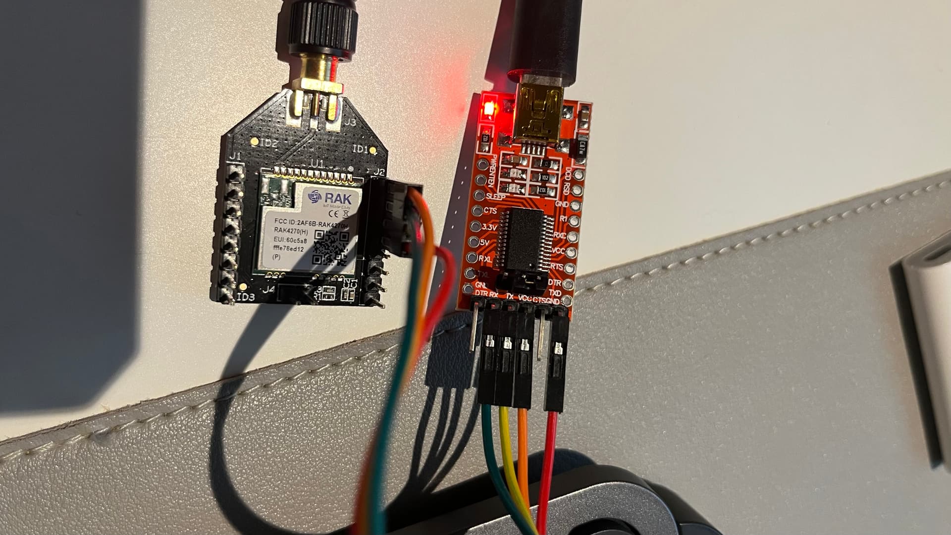
Setup: RAK4200 breakoutboard + Raspberry pi pico

Server: TTN v3

Details:

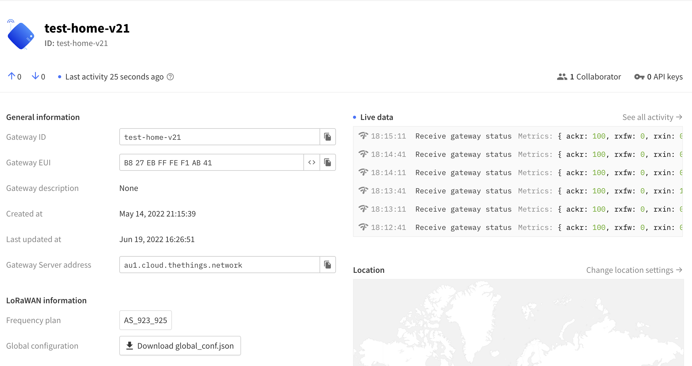
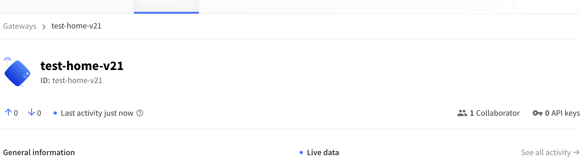
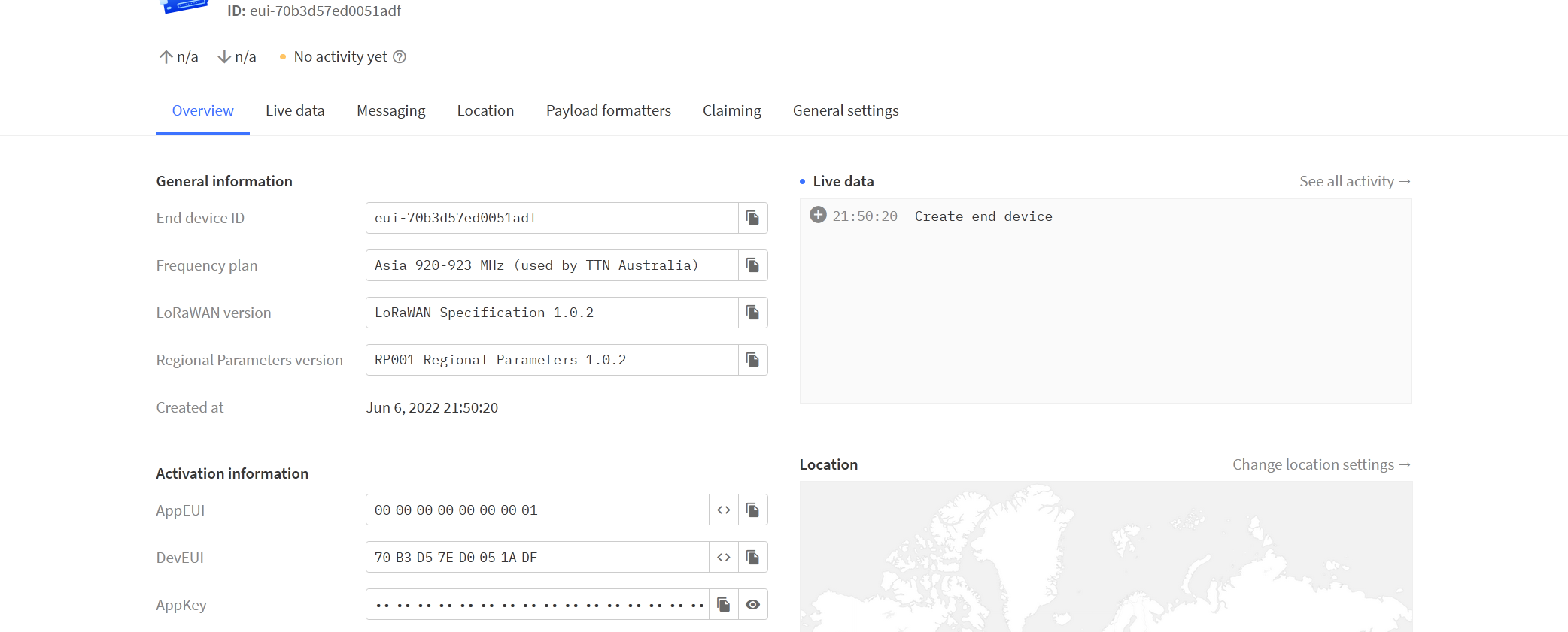
Hi all, I am very new to LoRa. I tried to use RAK4200 breakout board with pico as the LoRa end node, but I couldn’t get it work for couple of weeks… I have a gateway successfully connected to TTN in range as image below:

I followed the this guide: Raspberry Pi Pico Lorawan connection using RAK4200/RAK4270 Wisduo Breakout Board

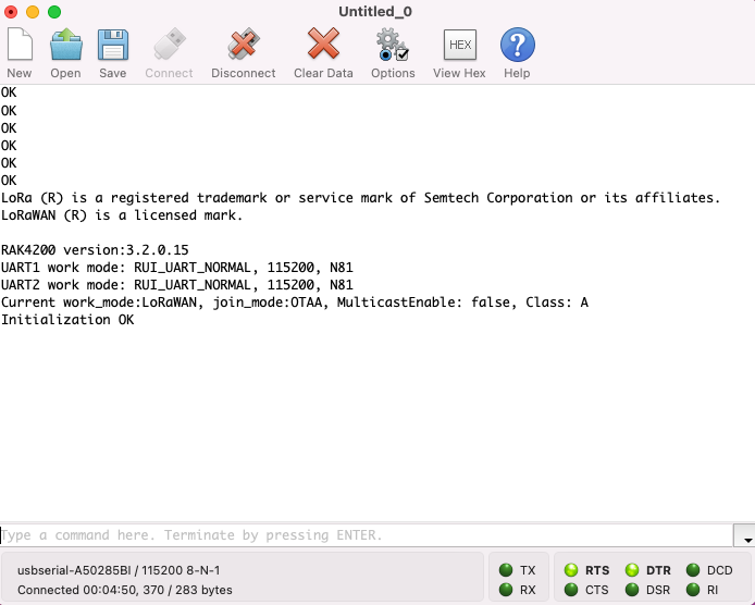
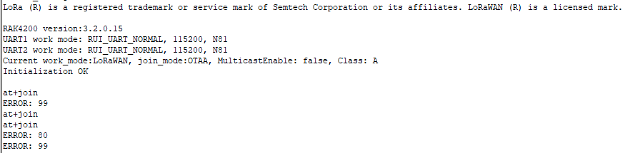
However, I got error like this:

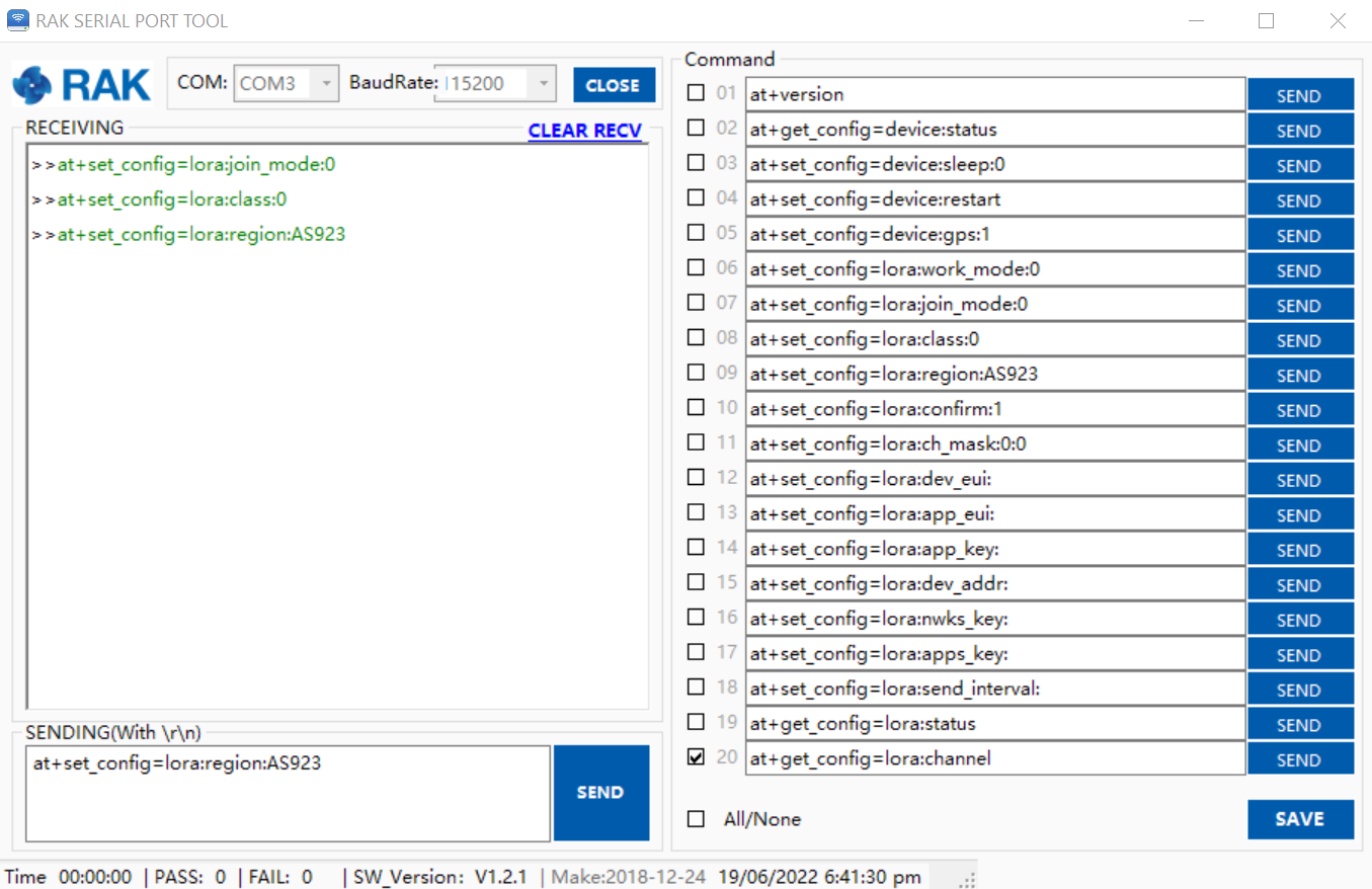
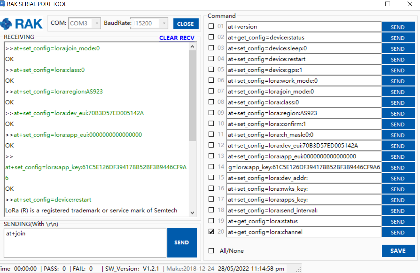
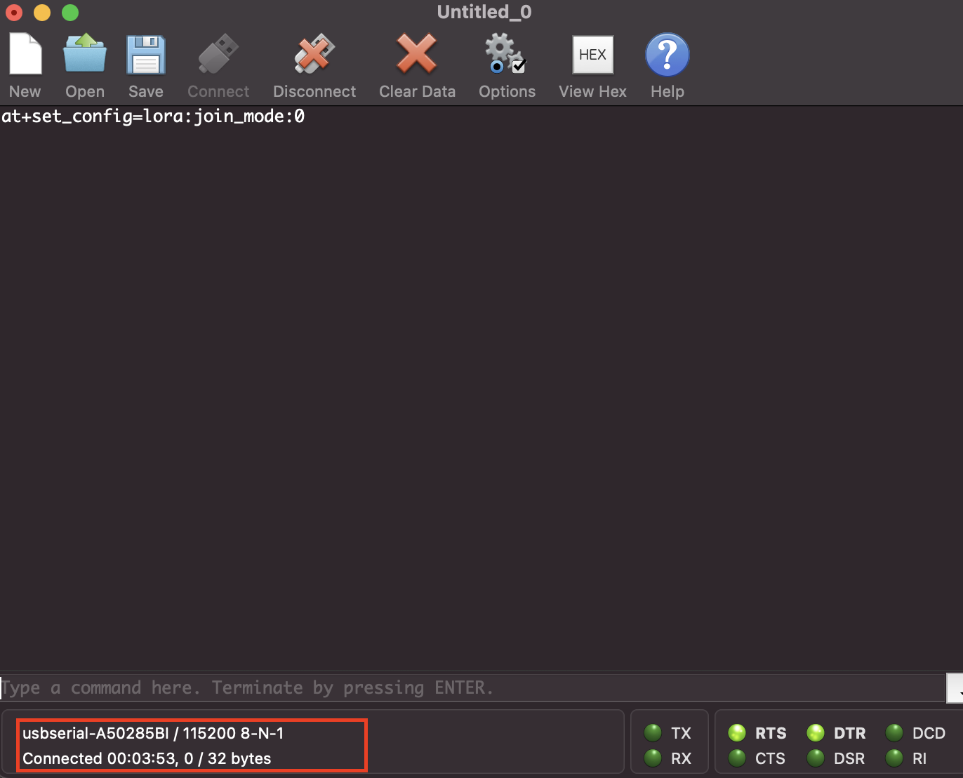
Then I used the RAK Serial Port Tool with UART to USB adapter and followed the official guide: RAK4200 Breakout Board Quick Start Guide #

At first all commands appear to have been sent successfully, but when I send at+ Join, the Serial Port Tool freezes without any response. I tried many times and got stuck sending “at+join”:

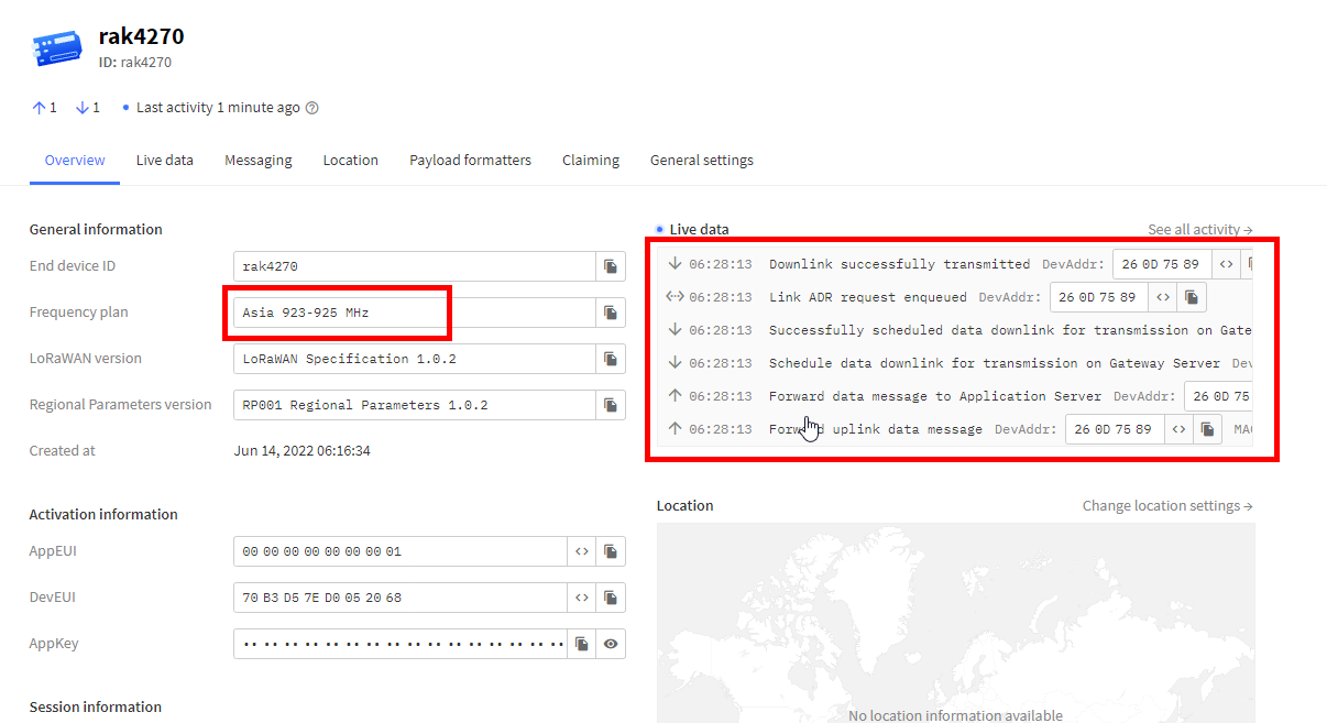
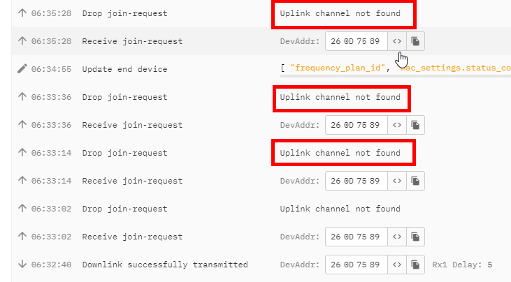
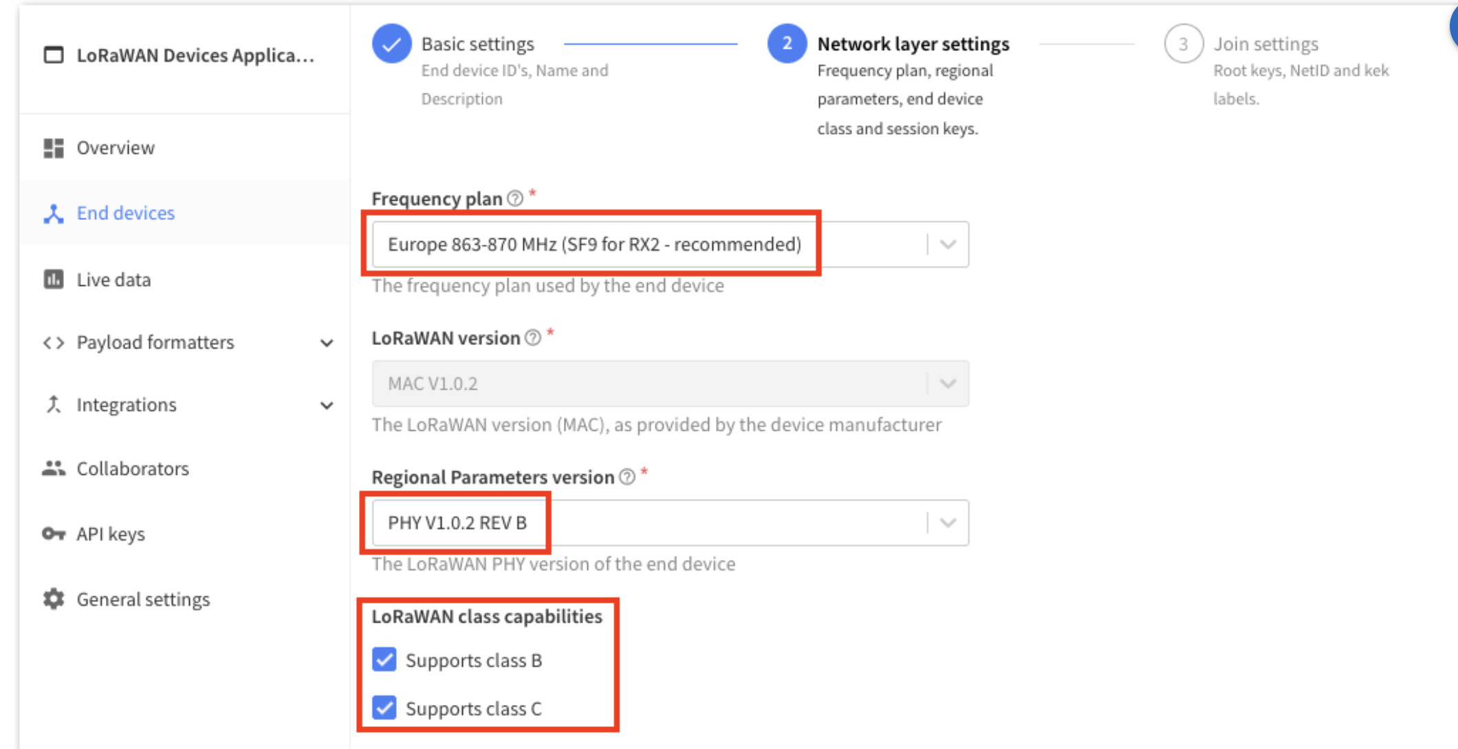
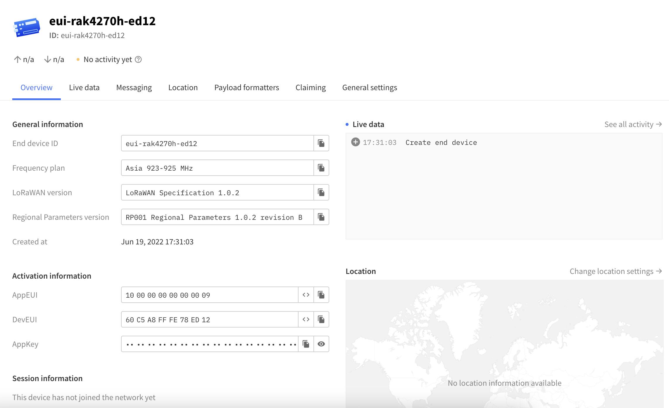
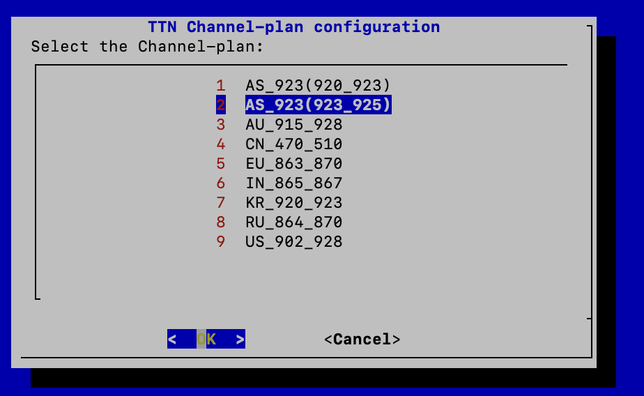
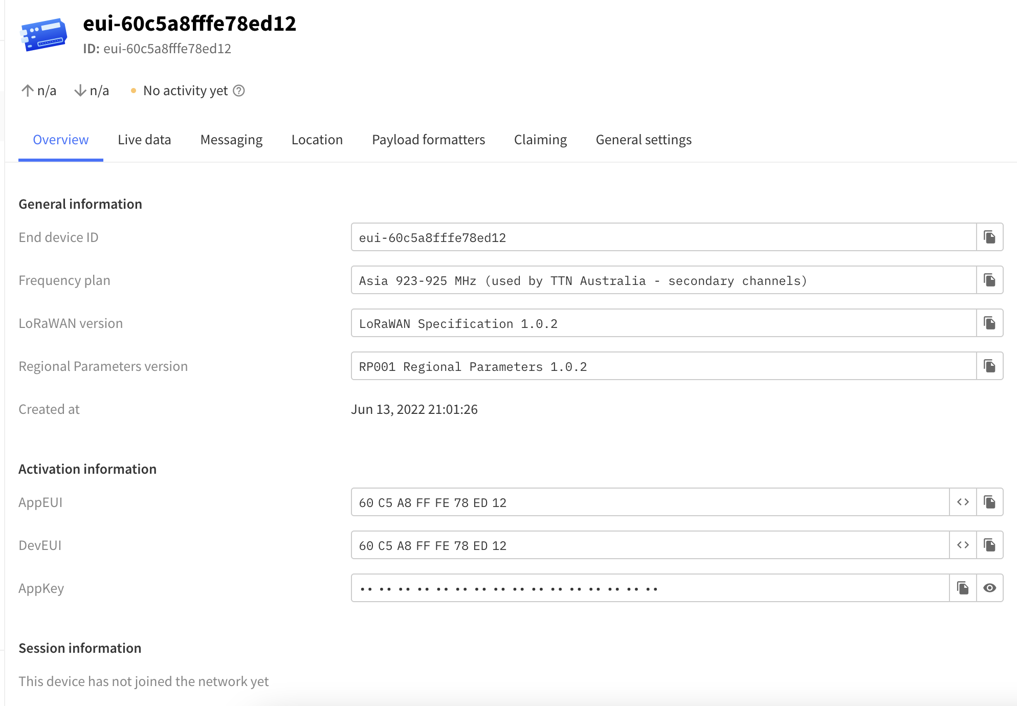
Here are all the settings on TTN v3 and the ouput of Serial Port Tool:

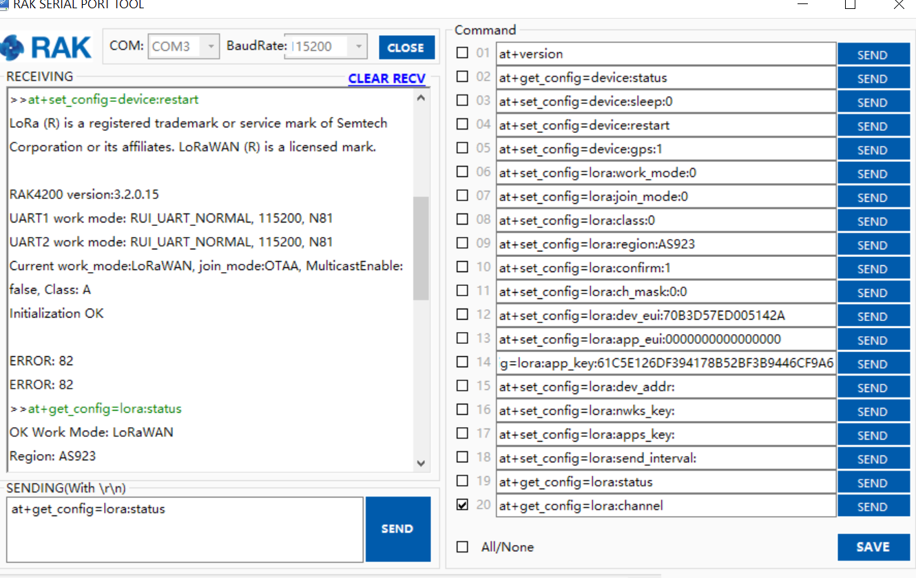
at+get_config=lora:status
OK Work Mode: LoRaWAN
Region: AS923
MulticastEnable: false
DutycycleEnable: false
Send_repeat_cnt: 0
Join_mode: OTAA
DevEui: 70B3D57ED005142A
AppEui: 0000000000000000
AppKey: 61C5E126DF394178B52BF3B9446CF9A6
Class: A
Joined Network:false
IsConfirm: unconfirm
AdrEnable: true
EnableRepeaterSupport: false
RX2_CHANNEL_FREQUENCY: 923200000, RX2_CHANNEL_DR:2
RX_WINDOW_DURATION: 3000ms
RECEIVE_DELAY_1: 1000ms
RECEIVE_DELAY_2: 2000ms
JOIN_ACCEPT_DELAY_1: 5000ms
JOIN_ACCEPT_DELAY_2: 6000ms
Current Datarate: 5
Primeval Datarate: 5
ChannelsTxPower: 0
UpLinkCounter: 0
DownLinkCounter: 0

I tried my best to search and find solution before I came here to ask for help. But, it’s really frustrating that I could’t even find out where is the issue… Any help or advice would be greatly appreciated! Thank you all in advance!!! :sunny:

On your RP2040 python issue, can you check if there is really a UART output on the TX pin of the RP2040 chip? Also if there is TX data coming from the RAK4200? It looks like there is no data being decoded.

On the second issue, can you try to on-board the device again but APPEUI must not be all-zero.

Hi @carlrowan,thanks for your reply.

Yes, I tried to print the “decoded_data”, and it’s none. I use your RP2040 with rak4200 tutorial, which is the same code thatt you provided here: Raspberry Pi Pico Lorawan connection using RAK4200/RAK4270 Wisduo Breakout Board

Do I need to connect a sensor with RP2040 and RAK4200, to send data? Sorry in advance, if my questions are too basic, I am really new to this.

For your second suggestion, I changed APPEUI as 0000000000000001, unfortunately still couldn’t sent the “at+join” command when I use the RAK Serial Port tool. So I couldn’t move forward to connect the device to the TTN v3 as well.

Hi @ays_Ibs ,

At this point, we should probably focus first to make your RAK4200 connect to TTN by sending direct AT commands. What can go wrong? Hmm. Things to check.

  1. Doublecheck EUIs/KEY - appeui(must not be all zero), deveui, appkey
  2. Do you have access to the gateway? Can you see if the packet is received?
  3. Is the region correct?
  4. Can you verify that other device can connect to your TTN application via the gateway you are using (just to isolate where the issue is coming from - if on the device, gateway or network server).

Hi @carlrowan,thanks for your reply.

To answer your questions:
1.Yes, they are all correct. Please find the below screeshots.
2. Yes, I have. I can only see the gateway is connected.
3. I think the region is correct, I set the device resion same as the gateway region.
4. I used a brand new rak4200 breakout board, but unfortunately, still the same issues. Below are the details of what I’ve done and the issues.

I bought 5 rak4200 breakouboard, and just used a new one as you suggested, added as the end device on TTN (below image 1), and I have access to the gateway, the gateway is successfully connected to the TTN(below image 2):

Here is the device setting on TTN:

Here is the gateway setting and Live data on TTN:

When I use the RAK Serial Port Tool, I can only send through the AT command on the right side comman window, as you can see in the image below, all the keys in the command window on the right are correct, as set on TTN (above image 1).

Since there is no command “at+ Join” in the command window on the right(yellow highlight in below image), I had to type “at+ Join” in a send window in the lower left (red highlight in below image). However, as you can see in the picture below, I clicked “send” but there was no response. Just like the problem I had with RAK Serial Port Tool before, I couldn’t send commands even though I changed to a brand new device.

It is worth mentioning that if I use the RAK Serial Port tool, I can only click “Send” in the right Command window of the software as I mentioned above to send the avaliable command on the tool (yellow highlight), and I failed to send any at command in the way of typing in the lower left window (red highlight ).

Hi @ays_Ibs ,

It can be a software bug that you can’t use the Send button.

Few things you can try:

  1. You can maximize the Serial Tool so you can see the at+join which is at the bottom
  2. You can change one of the commands in the right like modifying at+version to at+join then you can nose click the Send button.

Btw, you can also use other serial terminal tool like Termite, Teraterm, CoolTerm or even the Serial Moniotor of Arduino IDE.

Hi @carlrowan , thanks for your reply.

I used CoolTerm as you advised, but I still couldn’t receive any response after sending "at+join " command:

Hi @ays_Ibs ,

I just want to confirm that APPEUI is not all zero right? Then DEVEUI and APPKEY are same both on the network server and device?

I did some test and I can see errors if my parameters are wrong after sending at+join.

How long did you wait after sending at+join? When you send another at+join, you still don’t see any error?

Btw, I am testing using a US915 gateway and device.

Based on your screenshots, you configure TTN to work at AS920-923 for TTN AU.

The AU assignment of TTN is a bit messy/complicated because of its regulation (you can get more discussion about this in TTN forum).

Going to RAK4200, these are the channels of RAK4200 configured to AS923.

Are these frequencies you expect? Do you have other device already working (just a sanity check that you have a working setup)? Is the packet forwarder configured on your gateway same with the frequency band AS920-923 TTN AU?

Since the GW console in TTN doesn’t receive anything when you send at+join (it is literally empty and just shows the GW is connected to TTN), it is possible that there is mismatch on the Device (I’ve sent the channels above), the Gateway’s packet-forwarder and the Network Server (TTN) frequency configurations (either of these three) - on what channels are on/off and what specific frequencies.

Hi @carlrowan,

I am using the RAK2245 Pi Hat with Raspberry Pi 3b+ as the gateway.

For the gateway frequency plan, yes, you’re right, the AU assignment of TTN is a bit messy. In my case, only the second one AS_923(923_925 in RAK2245, with Asia 920-923 MHZ (used by TTN Australia) on TTN works for my gateway. If I select others, the gateway couldn’t connect to TTN at all:

So, I think the issue is not on the gateway.

To answer your first question:Yes, APPEUI is not all zero. I just gave it a another try, and I used another rak4200 device, and the setup the same dev_eui for the app_eui (below image 1), which I found it on the rak4200 package (below image 2) :

But, as you can see, I didn’t receive any response for even sent “at+set_config=lora:join_mode:0” after 3 mins:

I am really new to lora, and it’s quite frustrated that I encounter so many issues :cry:. So I wonder if it’s okay for you to help me via TeamViewer or we can discuss through Microsoft Teams when you have time? I am greatly appreciated for your help and reply.

Hi @ays_Ibs ,

On the gateway side, I tested it and only AS_923_925 works on that TTN Channel-plan. Both AS923 used by TTN Australia didn’t work.

My RAK4270 was able to join and send confirmed uplinks.

If you use any AS923 for TTN Australia, you will have channel issues on the device side.

I did this test to give you information.

But actually, I suspect that the problem is on your device side.

On the image you shared, it is RAK4270 and not RAK4200. They have the same breakout board btw.

But on the terminal software screenshot before, you showed RAK4200.

I am confused on what device you are using. Is it a mix of both RAK4200 and RAK4270?

I am just using RAK Serial Port Tool and not having any issue.

Can you validate that the USB-Serial convert you are using is ok? Also if the jumper wires you use for the connection is 100% working without issue of erratic discontinuity? Sometime these jumpers got lose and cause disconnections. Also, there are USB-Serial converters that are not ok specially the clones.

Hi @carlrowan, thank you so much for your detailed explanation. :smiling_face:

I checked the order, I misremembered the model I bought. The device I bought is 4270(H)-AS923: RAK4270 SX1262 Breakout Board for LoRaWAN | STM32l071 board – RAKwireless Store

So I then, started from beginning and followed the this Quick Start Guide, using OTAA and TTN v3:

I noticed that in your rak4270 TTN screen shot, you set the Regional parameters Version as “RP001 regional Parameters 1.0.2”, but in the Quick Start guide, it select “PHY V1.0.2 REV B” , ans also select “Support class B & C”. As I followed the guide, I choose the one with “Revision B”, is it wrong?

Here is the device TTN setting in Quick Start Guide:

Here is the my device TTN setting:

I also changed the frequency plan to AS923-925 as you suggested, luckily it works for my gateway. Here is the Gateway TTN setting:

I think you’re right, the issue probably is on the device end, I couldn’t receive any response after I send commands, whether it’s through the RAK Serial Port Tool or CoolTerm, below is the image of the mini USB to UART adapter I used, and I also changed the jumper wires for several times, but still couldn’t receive the response.

No response after sending commands:

Is there any other way I can solve these issues? Any advice would be much appreciated!! :smiling_face:

You are good in TTN as long as you choose 1.0.2.

The issue you have is on the device.

  1. Are the TX and RX connections ok? Not interchanged? It seems you have a working setup in your earlier posts.
  2. Have you checked the continuity of the jumper wires?
  3. I also use that FTDI USB-Serial board and got no problems but if you have other USB-Serial board there, you can probably test on that as well.

Without any response from the device, you cannot proceed on the TTN steps.