arriving soon. I’ve been trying to follow the quick start guide: doc.rakwireless.com/rak4260-wisduo-lora-module/quick-start-guide
and burning-the-firmware
I already have a j-link JTAG/SWD programmer/debugger as listed in the requirements, and as per this Q&A:
Q: Hello, I read de Quick Start Guide, but i dont understand if i need a j-link programer to program de evaluation board?
A: Yes you need the J-link. You can get one here: …emulator-kit Regards Vladislav
However the “burning-the-firmware” instructions say:
Connect the RAK50005 in your Windows PC using Micro USB Cable.
In the J-Flash software Menu Bar, Choose Target -> Connect
So why do I need the j-link?
And if I do need a j-link how to I connect it to the eval board?
A schematic for the 5005 baseboard would also be VERY helpful.
Thanks a lot.
Steve.
HI Steve,
The USB Cable connect to the PC just to provide the power supply when programming using Jlink.Afer finished program and disconnected jlink the USB port can be used as UART port.
Thanks for the clarification, it makes sense. BUT how does the j-link connect to the baseboard? I can see none of the standard JTAG/SWD 20pin or 10pin headers, so do I need to make up a special cable? If so what is the specification for the cable?
And where can I find a schematic for the 5005 baseboard?
Thanks again.
Thanks Mike. Sorry I missed your thread, should have spotted it. The answer finally makes sense but cant imagine why this is not in the documentation (such as it is).
Also, what a shame RAK didn’t adopt Microhip’s Xplained board wiring for PB03, PA28 & PA09, then we could have simply used all the Xplained board example codes without modification. Did you see that there’s code for a serial bootloader available from Microchip, so if that could be programmed with J-link it would avoid the need for jlink down the line. If I can get this to work I’ll let you know, but if you beat me to it perhaps you could let me know - I’m still waiting for my eval board.
Thanks again, Steve.
Well Steve, you are waiting for your eval board and I’m waiting for the j-Link Programmer
Yeh you’re right, RAK is missing many things especially documentation, Also I tried to ask for 5005 board schematics so I can develop some sensors boards but still got no answer
Guess they are very exited to launch new dev boards before others do, and they are not focusing on the documentation issue.
Anyway guess the RAK4260 chip is nice step forward just needs some time.
Will keep you informed if I got any progress
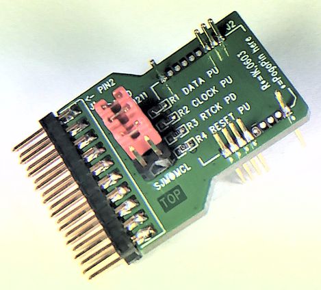
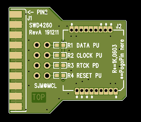
Have just knocked up a JTAG -> RAK4260 converter board which uses a 20pin pin-header and 9 pogo pins to connect directly to any in-system 4260 module to allow programming etc.
JLCPCB are currently making 5 (@ ~ 30UKpence each) for me. If you’re interested I can share the gerber files & if you’re in the UK can post you a PCB!
Steve.
Yes, I’ve actually published this on my own web site at: http://www.marvellconsultants.co.uk/LoRaNode/index.html
on which I’ll also be publishing my journey to developing a working LoRa node based on the brilliant RAK4260.
Hi Tony, sorry about that, I had some IP ranges blocked due to hacker activity, I’ve now removed those blocks so the site should now work for you - please let me know if not.
Yes, exactly what it’s designed for. I do have some spare boards, happy to post one out to you if you’re in the UK - steve at marvellconsultants dot com.
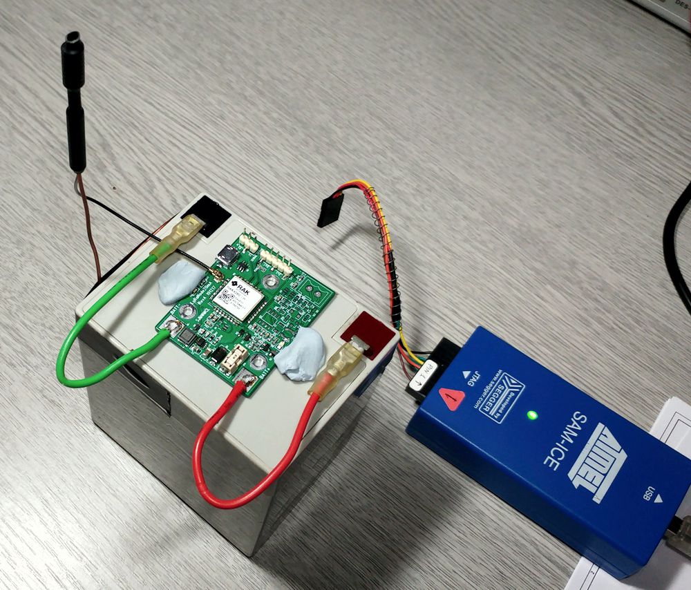
Mike, how are you progressing? I’ve now got my custom-built 4-20mA sensor node basically working but am struggling with radio reliability, at times all is fine but at other times lots of re-trys, downlink failures and re-joins
Hi @fishbeetle. I am testing a RAK4260 and sometimes encountered some ACK issues (I am using confirmed uplinks). I thought it was an antenna problem, because I’m using a simple (home) board with no extreme worries about the antenna circuit. In the coming days, I will improve the antenna and check if this problem persists.
Ricardo, thanks for responding. My issues too are with the downlink, uplink seems fine. I’m seeing RSSIs of -123dBs on downlink data and confirmation packets at the 4260 when in good proximity to the gateway antenna, meanwhile uplink RSSIs reported by the gateway are at -90 to -100dB. My gateway is a RAK2247+RPi3B+ on EU868. I know that these issues do not manifest themselves for AU band users running the same software (based on RAK’s demo code). Are you using RAK’s 4260 eval board and their demo code, or something you’ve developed yourself? Are you on EU868 band?
BTW I use this code to get the node’s RRSI data:
Hello Steve
I am working with Kerlink Gateway on the roof of my lab (two floors above) and using AU915 planning. I am currently changing the RAK code successfully. Today, I didn’t lose any downlink packages, but yesterday I lost some. I implemented the RSSI command you provided and compared the values: -100dBm on uplinks and -103dBm on downlinks. Looks like it’s ok.


 PCB!
PCB!