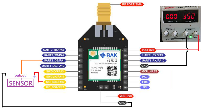
Setup: Rak4270 breakout board
With the use of 1pin as GPIO output and 1pin as Adc
Server: Chirpstack
Details:
I follow below link to set sleep mode
Inside my script, i already set GPIO to low in between uplink and sleep start
RUI_LOG_PRINTF(“Send data\r\n”);
ret_code = rui_lora_send(AppPort, AppData, AppLen);
Here ==> rui_gpio_rw(RUI_IF_WRITE, &gpio_output, &pin_low);
if (ret_code != RUI_STATUS_OK)
{
rui_timer_start(&user_sleep_timer); // If send fails, start the timer and wait for the next send.
}
However, the device join and uplink once, then no more data uplink. At the same time, I check with the GPIO status and it is still in High
What GPIO are you using? What is your payload? Do you have any connection in UART1_RX and UART2_RX or are these pins empty? These UART RX pins will be pulled-down during sleep automatically and any high signal trigger will wakeup the RAK4270.
Hmm. Were you able to test the RUI example without modification? It didn’t work too? Btw, I assume no USB-UART converted connected to any UART lines during your test.
I already set gpio_out to low then it goes to sleep mode. But, the RAK4270 breakout board still stop uplink or even stopped counting the send interval (no voltage output from gpio output) after 4 hours.
Do I understand it that the unmodified code stops sending at 4hrs? I can do the test myself to check if you confirm.
What did you add and where did you add it? Is it the same on your original post?
Hmm. Can you try if your RAK4270 device with sensor connection will wakeup if you set sleep interval? Remove first any LoRaWAN components. Just the sleep routine?
Or even just have a blinking LED with sleep functionality? If your device can’t wakeup even without LoRaWAN, then the issue is starting from sleep and not the uplinks.
Also, is the sensor current consumption without the output current rating of the GPIO pin of the module? It should be the same with STM32’s output current. Why not power it first externally for isolation and test? Might not be the reason but that is also one of the modification in the setup.
You can probably isolate the issue by making individual functionalities work first likec the ADC reading, GPIO setup, Sleep route, LoRaWAN, etc.
I’ve tried the unmodified code except that input my app_key for the server recognition.
But the board keep on uplink within the send_interval and no uplink after 4 hours.
I have similar experience in my customized firmware which activate a gpio out pin and adc pin . the longest operation time is nearly 15 hours. That’s why this time i try the unmodified code.