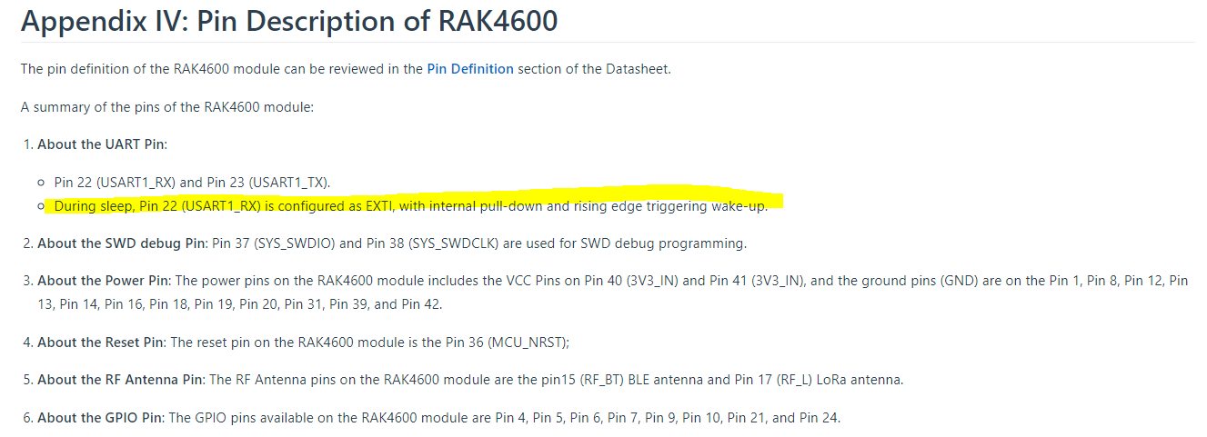
Issue: RAK4600 not always wakes up with a rising edge in pin 22 (USART1_RX)-
Setup: Hardware level:
Custom board: supply voltage = 3.3V, bypass capacitor is being used. Serial pins are connected directly to a microcontroller. Both microncontroller and RAK4600 have the same supply and voltage logic levels.
Serial configuration is the default: 115200 baud, 8 bits, no parity bit, and 1 stop bit.
Firmware/software level: A finite state machine is being used to control the power modes of the RAK4600. When the LoRa module is sleeping (not being used), TX pin from the microcontroller is set as OUTPUT LOW (because of the pull-down resistor on the LoRa module side). When the LoRa module is needed again, the TX pin of the microcontroller goes HIGH, waits two seconds, and then is configured as SERIAL to continue communication.
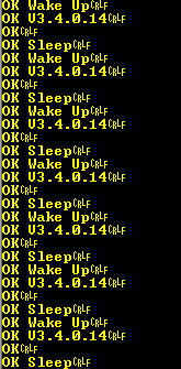
Details: After the rising edge is generated, most of the times I receive an “OK Wake Up\n\r” immediately (I’m using a “spy” serial terminal to watch what’s going on in the serial lines), but sometimes this doesn’t happen and it takes several seconds (20-30) for the LoRa module to respond “OK Wake Up\n\r”.
The image below doesn’t show the issue (as there are not time marks) but illustrates my program “flow”.
LoRa module is sleeping and is waken up by the rising edge.
Check the version in order to confirm if the module has wakened up.
Send some AT command (e.g Configure ADR, Duty Cycle, etc).
Set the LoRa module back to sleep state.
(In the image you can check the firmware version I’m using: V3.4.0.14)
I’ve checked the rising edge with an oscilloscope and it is always fine, even when the LoRaWAN module doesn’t respond immediately.
I’ll appreciate any suggestions to solve this issue.
Could this be a bug in RAK4600’s firmware?
EDIT: I have several custom boards and the issue happens in all of them.
What is the interval from sleeping and waking up? It is fix or can be trigger anytime by an external event? If trigger any time, what is the shortest trigger interval?
On the scope, is the RX pin of the RAK4600 clean on transitions? No signal bounces? How low is the “Low” voltage level? And how high is the “High” voltage level?
Do you have a USB-UART converter connected on the RX of RAK4600 (TX of the MCU) when doing the test? I am just thinking that it could affect the signals.
The time from wake-up mode to sleep mode is a little more than 2 seconds always, due to the FSM. The time from sleep mode to wake-up mode is at least 50mS (the microcontroller waits for 50mS between any two AT commands), but this is the worst-case since waking up is triggered by a user action, and this shouldn’t be very fast.
On the scope the RX pin of the RAK4600 is clean on transitions, there are no signal bounces. The LOW voltage is 0.0V and the HIGH voltage is 3.26-3.3V.
I have the RX pin of a USB-UART converter connected to the TX pin of the RAK4600 (RX pin of MCU), this way I can “spy” when the RAK4600 has wakened up, and I think it has no negative effect on the signals.
The issue of the RAK4600 not waking up immediately happens even when there is no USB-UART converter on the communication lines.
Something I just realized is that I was assuming that the RAK4600 TX signal was staying HIGH in sleep mode, but this isn’t the case as the RAK4600’s TX pin has 0.0V in sleep mode. RAK4600’s documentation is clear with the RX pin, but not with the TX pin:
I assumed that this pin was in UART idle (HIGH), so I was configuring my MCU RX pin with a pull-up.
UPDATE:
I’ve spent several hours changing and testing this. My wake-up/sleep flow now looks like this:
RAK4600 is sleeping.
MCU configuration:
SERIAL interface disabled
TX as OUTPUT LOW
RX as INPUT with pull-down
When a trigger by the user is detected the RAK4600 is wakened up as follows:
-MCU RX pin is set as SERIAL so I can detect when the RAK4600 sends “OK Wake Up”
-MCU TX pin goes HIGH to trigger the rising edge in the RAK4600.
-Wait until “OK Wake up” is received or until an MCU timer reaches 2 seconds.
-Set MCU TX pin as serial so we can send AT commands to the RAK4600.
Send some AT command.
Back to sleep with the following instructions:
-Send “at+sleep”
-Wait for the “OK” response for the “at+sleep”
-Set MCU:
SERIAL interface disabled
TX as OUTPUT LOW
RX as INPUT with pull-down
The problem is still present, sometimes it can take up to 50 seconds for the RAK4600 to send “OK Wake Up”
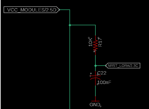
By the way, RAK4600’s reset pin is not being used but it is connected to the MCU with the following circuit:
NRST_LORA signal is connected to pin 36 of the RAK4600 and to an MCU’s GPIO. The MCU sets this pin as HIGH with 3.3V and is never set to LOW.
VCC_MODULES is 3.3V.
Things that are intermittent are harder to troubleshoot. If the issues don’t always happen or if the timing differs, it is harder to determine if it is FW issue unless we see some kind of pattern.
Btw, the MCU RX pin can be set as UART RX pin for the entire flow since it is still an input pin and in high impedance state.
I am confused on the part where the MCU will wait for “OK Wake up” or until the MCU reaches 2 seconds. If it escapes the 2-second mark, how were you able to measure the 50 seconds?
Also, have you tried giving more than one rising edge to wake up?
Btw, the MCU RX pin can be set as UART RX pin for the entire flow since it is still an input pin and in high impedance state.
Actually, about the MCU RX pin set as UART RX for the entire flow: this isn’t recommended by the MCU’s manufacturer since it can increase power consumption (compared to configuring the pin as GPIO) and my custom board is being powered from 2AA batteries, so any power optimization is necessary to achieve a long battery autonomy.
While the RAK4600 is sleep, the MCU should also be in sleep mode (low power) unless it is executing something else.
I am confused on the part where the MCU will wait for “OK Wake up” or until the MCU reaches 2 seconds. If it escapes the 2-second mark, how were you able to measure the 50 seconds?
The 2-second mark is to avoid blocking an MCU “process” waiting for a response (“OK Wake Up”) that might not arrive, so after 2-seconds the MCU gives a “TIMEOUT” response to an Android app that’s used to interact with my custom board (included RAK4600’s configuration). However, since I can’t cancel the waking up of the RAK4600, some seconds after the “TIMEOUT” response’s been sent to the Android app I still can see that the serial console (USB-UART converter) receives the “OK Wake Up” message.
I think that the issue is happening after N exact seconds from powering up the RAK4600. Besides that, I don’t have any clue. I’ll be doing some other tests to determine the value of N (if it’s fixed).
A workaround could be waiting for at least 60 seconds instead of 2 seconds.
Yes, I’ve tried multiple rising edges (2 and 3 rising edges with these characteristics: 2ms HIGH and 2ms LOW, sometimes 10ms in each state) with no success.
UPDATE:
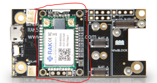
I’ve tested using the RAK4600 Evaluation Board but the problem also appeared.
The setup used for the test was:
-Just the little board that’s soldered to the RAK4600 was used, the one marked in red in the image:
-I soldered wires to RX and TX pins of the RAK4600.
-Connected RX and TX signals to another board and powered the RAK4600 from the same board. This “board” is different than the one described in the initial question of the post.
So far I haven’t found any pattern in the problem. It just seems to happen at any time. However, in some tests I did, the problem seemed to appear after exactly 2 minutes of powering the RAK4600. But in other tests this didn’t happen so I can not get any conclusion from that.
I’ll appreciate any suggestions.
Perhaps there is a newer firmware version I can try, and hopefully it’ll solve the issue? (considering is a RAK4600 firmware issue).
I think is the same version I have installed, however, I will try to install the hex file from the link.
Here’s the program flow I’ve been testing lately:
Power MCU and RAK4600
MCU RX and TX pins are configured as UART.
MCU waits 2 seconds for the RAK to initialize, then MCU sends “at+set_config=device:sleep:1”.
500mS after receiving the “OK Sleep” response from the RAK4600, the MCU RX pin is configured as GPIO INPUT without any pull resistor, MCU TX pin is configured as GPIO OUTPUT LOW.
When a user trigger is detected (let’s say a button), the MCU configures its RX pin as SERIAL (to listen for “OK Wake Up”). Then, MCU’s TX pin changes its state to HIGH for triggering RAK4600’s wake up interrupt.
Once the MCU receives the “OK Wake Up” response, it configures its TX pin as SERIAL.
Wait for 500mS to send any other command.
MCU sends “at+set_config=lora:adr:1” and waits for “OK” response.
MCU receives the “OK” response and waits for 500mS to send any other command.
MCU sends “at+set_config=device:sleep:1”.
500mS after receiving the “OK Sleep” response from the RAK4600, the MCU RX pin is configured as GPIO INPUT without any pull resistor, MCU TX pin is configured as GPIO OUTPUT LOW.
Go to step 5. to wait for a user trigger.
Hope that the steps are clear. Thank you for your help.
Every 2 minute mark, I will have 1 minute long no Ok Wake Up reply. You can have a look on that.
Btw, if you don’t need BLE functionality, you can consider to use RAK4270. This is based on the latest SX1262 LoRA RF chipset and STM32. This WisDuo module do not have this issue.