Not sure if this is the right place to ask this, but I’m working on a design with the RAK4630 module. Wondering if I can have some clarification, below is the schematic for the RAK4631
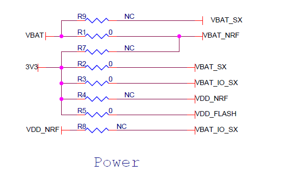
In the power section, there are two unpopulated 0 ohm resistors (I’ve highlighted them in yellow). These resistors would connect VDD_NRF to 3V3 and/or VBAT_IO_SX. Without these resistors VDD_NRF is left floating. I have confirmed that these resistors are not populated on the modules I have.
In the RAK4630 datasheet, it mentions to connect VDD_NRF to 3V3 if using a single 3.3V power supply or connect VDD_NRF and VBAT_IO_SX together in a battery setup.
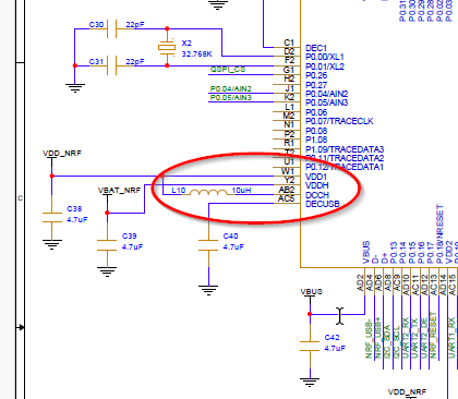
The RAK4630 module should be supplied as shown on the RAK4631 with two voltages, a 3.3V supply and a higher second voltage for the DCDC converter of the nRF52840.
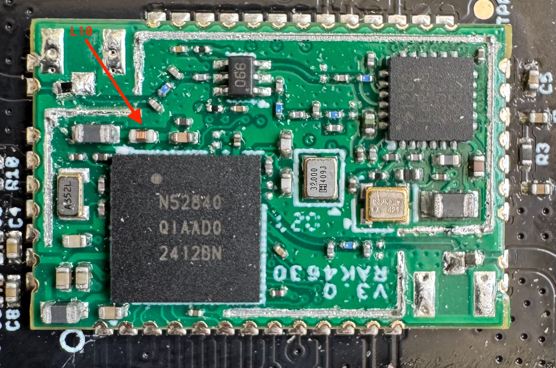
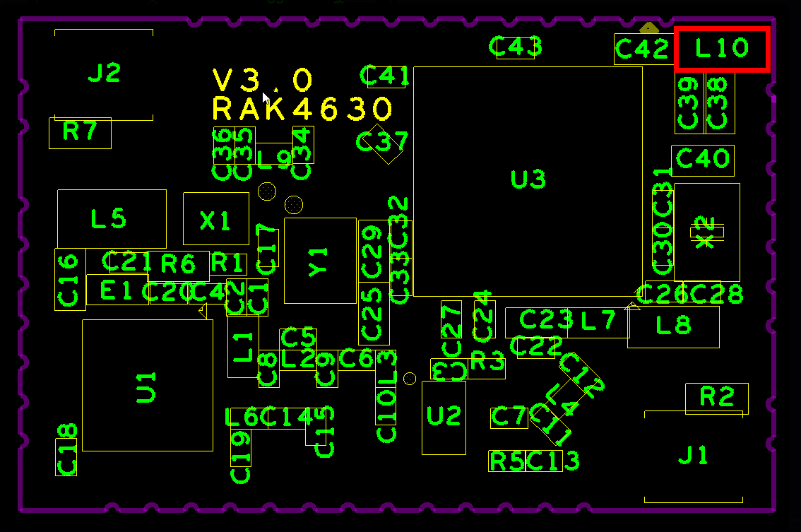
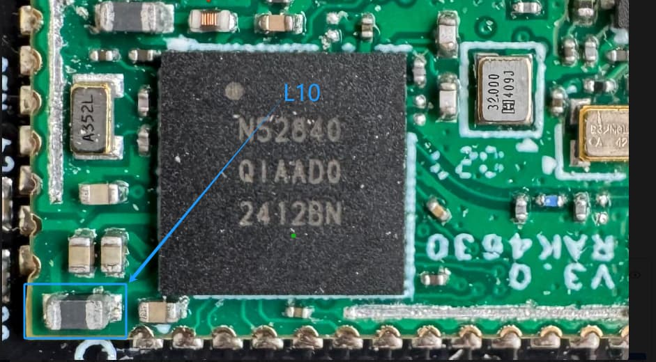
Single supply voltage requires a change on the RAK4630, but the component (L10) is under the metal hood, so it cannot be done easy.
We will be powering the RAK4630 with both 5V via VBUS and 3.3V via VBAT_NRF, VBAT_SX and VAT_IO_SX. Can you confirm if VDD_NRF should be connected to 3.3V?
L10 on the RAK4630 schematic shows it as NC so I would be skeptical if it’s actually populated? All the resistors labeled as NC are not populated.
Thanks, saw that yesterday
removing it cause some troubles, but I suspect DC/DC of REG0 not disabled, I’ll try today more investigation.
In the meantime I’ve tested things that make me more sense (from my point of view) about single power supply (let’s say up to 3.6V and call it VDD)
Connect VBAT_NRF and VBAT_SX to VDD
Leave VBAT_IO_SX and VDD_NRF floating
In this case this is the first stage of NRF52840 REG0 that will power out VBAT_IO_SX and VDD_NRF
Tested and works like a charm with 5uA with latest Sidewalk sample code.
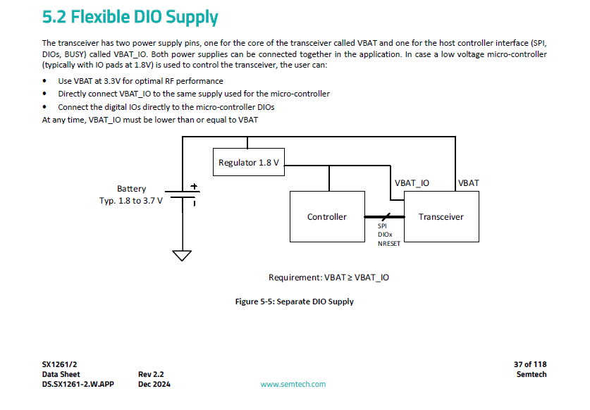
Is there a specific reason you left VBAT_IO floating? From the SX1262 datasheet it appears that it needs to be powered from VDD (or the voltage of the MCU the IO pins are connected to). I would think leaving it floating would cause issues on the DIO pins .
Leave VBAT_IO_SX and VDD_NRF floating but tied together, as VDD_NRF is provided by REG0 it will also power VBAT_IO_SX
A lot of options there, all linked together making things complex to understand, 4 NRF powering ways, RAK4630 wiring between supply lines adding L10 not L10 oprion, Zephyr/NRF SDK setup option (REG0, REG1) and finally your PCB routing setup
Anyway, about Low Power testing, I just suspect a bad RAK4630 module, it works but draw approx 40uA in sleep mode and same firmware on other RAK4630 modules give me 5uA. I unsoldered all components on our PCB leaving only RAK4630 to see what component was the issue, but no luck it was just the RAK4630 (that was working BTW)