RAK4631+19007+13010 pinMode (WB_IO1, OUTPUT) isn't working

Please include the following information, in order for us to help you as effectively as possible.

  • What product do you wish to discuss? RAK4631, RAK3372, RAK11200, RAK11310, RAK11722? The subject RAK4631 core + RAK19007 base + RAK13010 SDI-12 IO module works okay. But I tried to use pinMode (WB_IO1, OUTPUT) to send coded pulses for various changes in state of the LoRaWAN and SDI-12 sensor readings to an externally mounted IP67 LED. This won’t output a signal even if I simply try to turn the LED on/off after void setup( ) via void loop() code. What kind of conflict might be occurring that I am missing? And if this is an interrupt or SDI-12/ LoRaWAN conflict issue, is there a way to work around this? The reason I am asking is that I am porting this to a solar powered battery charger enclosure with an external IP67 reset switch and the indicator to provide external status.

  • What firmware are you using? (RUI3 or Arduino BSP or other IDE (e.g. STM32CubeIDE)? I’m using the Arduino BSP and IDE with UF2 Bootloader 0.4.4
    Model: WisBlock RAK4631 Board
    Board-ID: WisBlock-RAK4631-Board
    Date: Jun 17 2026
    Ver: 0.4.4
    SoftDevice: S140 6.1.1 and appropriate Arduino RAKwireless libraries.

  • What firmware version? Can it be obtained with AT+VER=?

  • Computer OS? (MacOS, Linux, Windows) Windows 10

  • What Computer OS version? Latest Windows 10 with extended security updates

  • How often does the problem happen?

  • How can we replicate the problem? I don’t think so, because you folks don’t have any similar SDI-12 sensors.

  • Provide source code if custom firmware is used or link to example if RAKwireless example code is used.
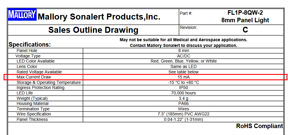
What exactly is the IP67 LED?
Manufacturer, supply voltage, required current to power the LED.
GPIO’s current is limited, it might not be enough the drive the LED directly. Even the small LED’s on the BaseBoard are driven through a transistor and not directly from a GPIO.

Hi, beegee - I’m attempting to drive a FILN Model FL1P-08QW-2 green LED rated 5/12–24V @ 0.2W. I connected this LED via breadboard using 560-ohm series resistor and drove it using the same output, but the sketch I ran was the RAK4631 sketch, Read_Battery_Level.ino. I added
this code as a test of the same LED, which worked okay.
Example:
#define PIN_GRN WB_IO1

void setup() {…

pinMode(PIN_GRN, OUTPUT);
digitalWrite(PIN_GRN, LOW); 
...

}
void loop() {…
digitalWrite(PIN_GRN, HIGH);
delay(1000);
digitalWrite(PIN_GRN, LOW);
delay(3000);
}

I then ported this code to my LoRaWAN-SDI-12 sketch, but the same LED did not light. The next thing I did was hookup the Saleae Logic probe (8-input-type) to see if I could capture a pulse. Nothing there, but I could see that changing setup low to high changed the pin level. What doesn’t appear to work is the way - or where - I coded the pin.

The next thing I tried was to create a similar dual IO base jig with one port the SDI-12 IO module (RAK13010) and the second port being a breakout board, Model RAK13002.

I did use a similar dual IO board to verify I could get the same LED to light, but it did not have the SDI-12 IO module on it. It used the same Read_Battery_Level.ino like above which suggests to me that there is sufficient drive to operate the LED. The LED is diffused, but very discernible go on-&-off in bright daylight.

When I loaded the LoRaWAN-Dual-SDI-12 sensor sketch, I used an Arduino UNO R3 as a dual SDI-12 TEROS22 sensor to respond to the queries. That data is very realistic. The LoRaWAN payload is then sent to TTN join network server and the end device payload formatter, a custom JavaScript, decodes the data correctly.

Here is the simulator sketch which uses GPIO Pin 7 connected to the SDI-12 Data line and the UNO R3 GND connected to the SDI-12 GND connection. (12V is not used with this simulator making it easier to work with instead of the actual sensors because they require 12V - and are pricey (hundreds of dollars).
UNO_R3_Dual_SDI_12_Sensor_Simulator_v6_copy_20260928235901.ino (3.5 KB)

Anyway, if there are limits to the outputs, I even connected a 3.7V 5600mAh battery that was fully charged. It made no difference. It could also be that I’m not addressing the RAK13002 WB_IO1 breakout pin correctly. But that doesn’t make any sense since the other dual IO base jig worked okay.

If there is a better IO-module to drive LED’s I might consider that. The fact that neither SDI-12 or LoRaWAN join & payload timing is not affected suggests I’m missing something that isn’t showing using the Saleae LA.

I hope you might have a clue besides drive current, because I don’t actually have a way to measure the low current draw at this time since all the device voltages look stable on an o-scope.

Attachment: This is the TTN LoRaWAN sketch that I am using with the RAK4631 bench end device. It does contain remnants of the debugging Pin_Grn LED littered throughout. Still, it compiles and loads okay. Maybe it will be easier to use with the dual SDI-12 sensor simulator.
LoRaWAN_OTAA_ABP_rak4631-1_v4.ino (16.9 KB)

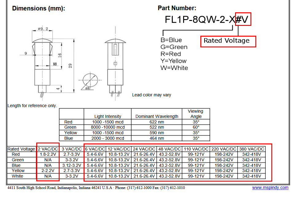
What is the exact rated voltage? This LED has many variants

But even if you have the FL1P-8QW-2-X3V for ~3V, the max current draw of 15mA is too high.

A nRF52840 can drive 4mA on its GPIO’s in normal mode. Even it might have worked, you are running here at the upper limits and might damage the GPIO.
That has nothing to do with a battery or not.

For the RAK13002, WB_IO1 is directly connected to the GPIO of the MCU.
RAK13010 does not use WB_IO1, so there is no conflict.

I can’t tell why it wouldn’t work, beside of the current limit.

Hi, beegee -

It took me a bit of time to gather the data you asked about.

The manufacturer’s website did not have specifications for these particular FILN Model Number FL1P-08QW-2, IP67 Waterproof, panel Indicators. They do publish a generic certified test copy of their white LED panel indicator.

Each of the three colored LEDs that I have contain internal series resistors as listed next: Green: 9.79k-ohm; Blue: 9.97k-ohm; & Red: 2.96k-ohm.

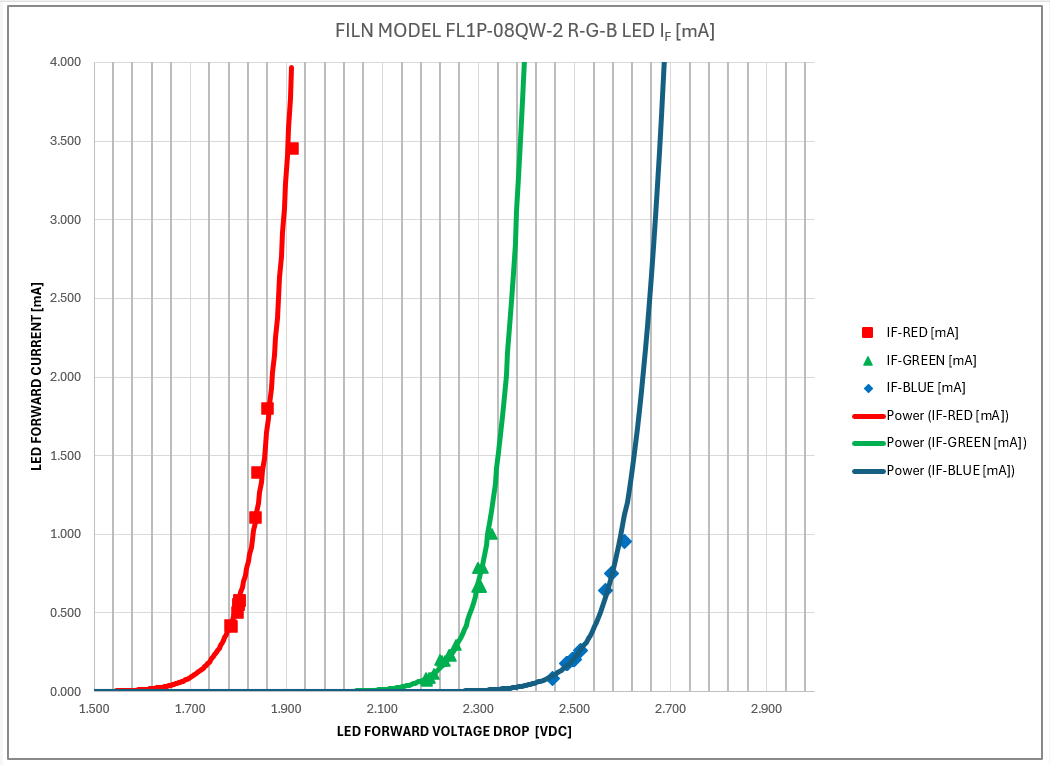
I measured electrical parameters for the three LED colors and enclosed a chart showing a chart of the LEDs forward DC current versus the LED forward DC voltage drop. (Measured test data is also attached.)

I have concluded that the RAK4631 MCU was not being overloaded by the green LED. Note: The FILN green LED panel indicator provided a satisfactory daylight-visible output in sunlight was visible in using the other two colors).

I did determine - as I mentioned previously - that I tested the panel indicators using the battery voltage sketch to verify code for use with MCU’s WB-IO1 GPIO output. However, I’m still stuck trying to get my LoRaWAN-SDI-12 sketch to work with the same pinMode setup and digitalWrite code. I haven’t yet stumbled across why. Any suggestions about what might be interfering with such a use after reviewing that sketch I sent you (along with the SDI-12 Arduino UNO R3 dual TEROS22 SDI-12 simulator sketch?

Respectfully,

“MichaelOboy” Overeem

FILN MODEL NUMBER FL1P-08QW-2 IP67 WATERPROOF LED PANEL INDICATOR ELECTRICAL PARAMETERS.docx (246 KB)

Your current diagram shows that at lower voltage it is already reaching the 4mA that the nRF52 can provide.

There is no conflict with WB_IO1 and the RAK13010 SDI module, so this is not the problem.

I can’t help further here, I do not have a working SDI12 setup nor do I have your LED.

Hi, beegee -

Based on your observation about the current still being too high, I obviously messed up.

The curve I sent just illustrated the LED voltage/current curves. Sorry about that!

My particular Red/Green/Blue LED combo package panel indicators were not listed on the manufacturer’s website using the only model number I received with the panel indicators I purchased.

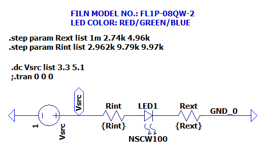
Therefore, I measured each color LED panel indicator using the values as illustrated in the SPICE sketch below:

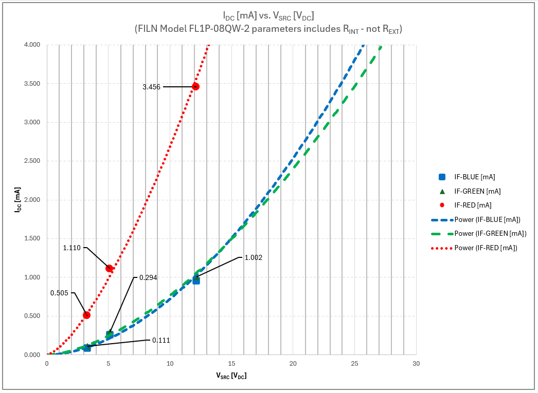
I previously sent you all the tabulated measurements but got off track with the data you wanted - the actual current at the actual voltage through the panel indicators.

This chart corrects that error by showing what I stated: None of the FILN panel indicators can overload the MCU with the particular internal resistor values they have. The associated color LEDS also exhibit adequate lumens for my purpose, but green stands out in daylight at 3.3V and/or 5.1V. (All the LEDs are daylight visible at 12V.)

So, this message is just to correct the previous email. Again - sorry for the confusion it caused.

Now I just have to figure out why there is no measured LA output from the same MCU running the integrated LoRaWAN-SDI12 sketch versus running the example battery voltage sketch. There is something I’m not identifying with the way the code is running. I’m still suspicious that there must be a timing or interrupt conflict caused by my use of delay() in the diagnostic panel indications I am trying to add to the RAK4631.

Thanks again for the timely response! I hope that this email actually sets the FILN panel indicator record straight about it NOT overloading the MCU’s 4mA maximum current rating.

Respectfully,

Michael Overeem