
Hi, I’m trying to connect DS18B20’s data wire to the WB_IO2 pin of the RAK19007 board.
Just using OneWire lib.
Seems that it does’t work.
Could you advise a correct lib for 1-Wire?
Welcome to RAK forum @saper ,
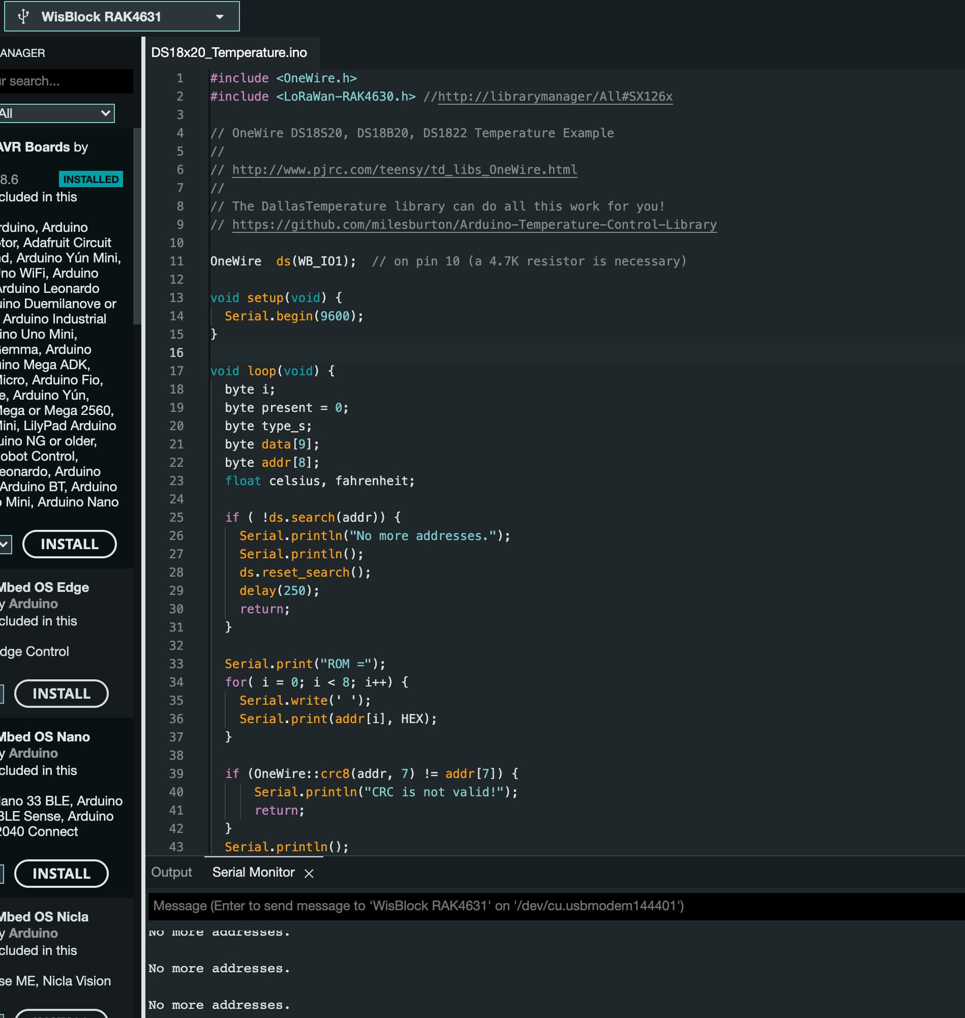
If you are using RAK4631 Arduino BSP and not RUI3, then the standard OneWire library will work. However you should use a different IO pin and not WB_IO2 since it is used to control 3V3_S line. You can try WB_IO1, WB_IO3 or WB_IO4.
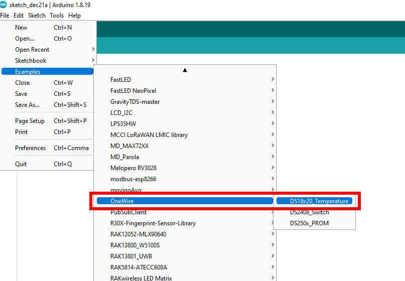
Thank you, @carlrowan, I tried with WB_IO1 and this example. It also doesn’t work.
I’ve got “No more addresses” in the output. The same set is perfectly working on ESP8266.
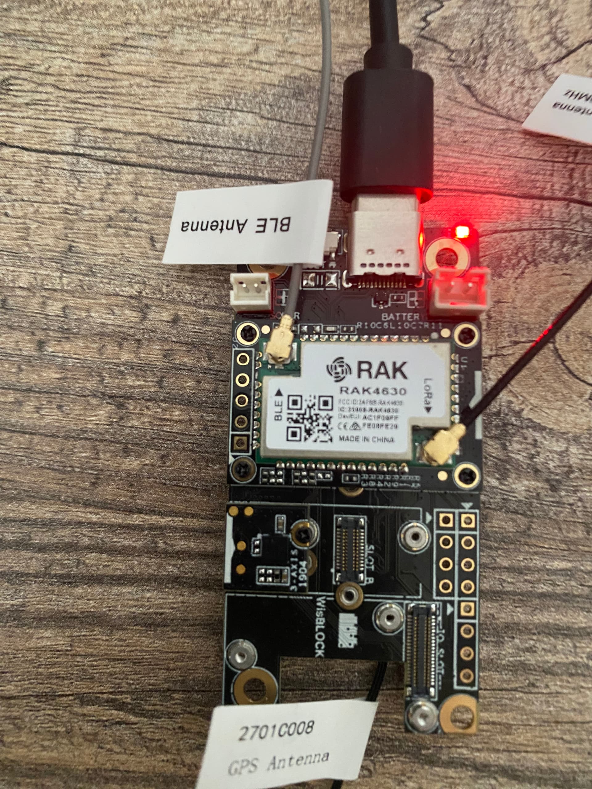
I have purchased a WisBlock Starter Kit (RAK19007 + RAK4631)
Hope that I’ve got an Arduino BSP. But it is marked as RAK4630 on the label.
How can I check to be sure that I’m using Arduino BSP and not RUI3?
And if it is RUI3 OneWire will not work? Should I try a 1-Wire - I2C bridge?
Hi @saper ,
You can use WB_IO1. The WB_IO3/4 is not exposed on the baseboard you use.
Few things to check:
- Pull up resistor on the signal line of DS18B20.
- Validate continuity on the 3 wire connection of sensor (VDD, GND, Signal).
Based on your error, it looks like the code compiled successfully but cant detect the address.
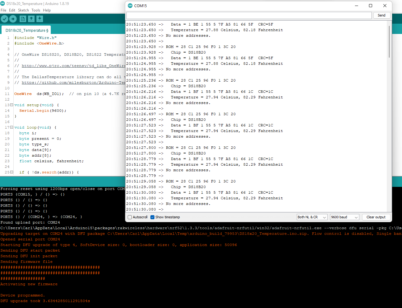
Yes, absolutely so.
Signal line is pulled up with 4.7K resistor to the VDD.
3 wire connection is correct also. VDD, GND, and signal to WB_IO1.
All the same works for ESP8266 if I put it there and when I return to 4631 it doesn’t.
That’s good to hear. I did a validation test and seems to work with mine. Anymore questions you have related to WisBlock, just let us know 
Sorry one more question.
Now I have joined standard RAK GPS Sensor (RAK 1910) to slot A and added setup code:
pinMode(WB_IO2, OUTPUT);
digitalWrite(WB_IO2, 0);
delay(1000);
digitalWrite(WB_IO2, 1);
delay(1000);
GPS_SENSOR.begin(9600);
while (!GPS_SENSOR)
;
And after that I have no 1-Wire data from DS18B20 and vice versa if I comment this block
/*
pinMode(WB_IO2, OUTPUT);
digitalWrite(WB_IO2, 0);
delay(1000);
digitalWrite(WB_IO2, 1);
delay(1000);
*/
then I will have 1-Wire data without GPS - it unable to read bytes from serial port in this case.
Do you have any ideas?
And can I use WB_SW1 as GPIO for 1-Wire?
@carlrowan as I read in the another topic @beegee told that 1910 uses both pins WB_IO1 and WB_IO2.
And in this case I need 13002 module. I understand that it is the easier and better solution.
But now I’m limited with time to deliver the solution and can’t wait for the delivery. So could I switch off the mode for GPS (1910) and switch it on periodically? Actually I need GPS data only few times a day or on specific events.
Hi @saper ,
You are using the 2nd generation baseboard - RAK19007.
You can use SLOT D at the back to connect your RAK1910. This will free up IO1 and IO2. The UART pins of SLOT D is same with SLOT A. It should work there. Hopefully you can still proceed quickly on your project 
1 Like
And finally everything is working when I used slot D and Serial1.
Thank you @carlrowan for your support!
1 Like
This topic was automatically closed 2 days after the last reply. New replies are no longer allowed.