RAK4631 no longer responds over SWD after interrupted NVMC programming — RAKDAP1 Unexpected ACK 0 / No ACK

Hello,

I need help recovering a RAK4631 WisBlock Core installed on a RAK19026 WisMesh Base.

The RAKDAP1 is brand new and previously worked correctly with this exact RAK4631. Before the failure, it successfully detected the nRF52840 and backed up the complete internal flash and UICR.

HARDWARE

Target:

  • RAK4631 WisBlock Core
  • RAK4630 / Nordic nRF52840 + SX1262
  • Installed on a RAK19026 WisMesh Base
  • LoRa antenna connected
  • Target powered separately through the RAK19026 USB-C port

Debug probe:

  • Official RAKWireless RAKDAP1
  • SKU: 910009
  • New device
  • Detected as ARM DAPLink CMSIS-DAP
  • USB VID:PID: 0d28:0204
  • Interface: CMSIS-DAP-v1-MuseLab
  • The full probe UID can be provided privately if required

HOST SOFTWARE

  • Kali Linux
  • pyOCD 0.45.1
  • Target explicitly selected with: -t nrf52840
  • RAKDAP1 selected by its unique probe ID
  • SWD frequencies tested: 100 kHz, 10 kHz and 5 kHz

RAKDAP1 DETAILS.TXT

  • Interface Version: 0254
  • Bootloader Version: 0254
  • Build Time: Nov 30 2019 15:39:08
  • HIC ID: 97969908
  • Git SHA: 241d432f83187de9ec2e0209972bf200010b5e8f
  • Local Mods: 1
  • Auto Reset: 1
  • Automation allowed: 1
  • Overflow detection: 1
  • DAPLink Mode: Interface
  • USB Interfaces: MSD, CDC, HID, WebUSB
  • Bootloader CRC: 0x76d78d7a
  • Interface CRC: 0x9cd5b2d6

WIRING

The wiring follows the official RAKDAP1 Quick Start Figure 15:

  • RAKDAP1 GND → RAK4631 GND
  • RAKDAP1 TCK/CK → RAK4631 SWDCLK
  • RAKDAP1 TMS/IO → RAK4631 SWDIO
  • RAKDAP1 3V3 → RAK4631 3V3
  • RAKDAP1 5V not connected
  • RESET not connected because the 1x4 pogo fixture only covers GND, SWDCLK, SWDIO and 3V3

Actual wire mapping:

  • Brown → GND
  • Red → TCK/CK / SWDCLK
  • Orange → TMS/IO / SWDIO
  • Yellow → 3V3
  • 5V remains unused

The four RAK4631 pads, with the base USB-C connector oriented upwards, are:

  • GND
  • SWDCLK
  • SWDIO
  • 3V3

The upper RESET pad remains outside the 1x4 pogo fixture.

OFFICIAL DOCUMENTATION USED

RAKDAP1 Quick Start:

The official diagram confirms:

  • TCK/CK → SWCLK
  • GND → GND
  • TMS/IO → SWDIO
  • 3V3 → 3V3
  • External target power

ELECTRICAL CHECKS

Target voltage:

  • 3.32 V measured between GND and 3V3

Continuity:

  • GND continuity verified
  • SWDIO continuity verified
  • SWDCLK continuity verified
  • Pogo wires checked individually
  • No 5V connection

Resistance measurements with the target completely unpowered, RAKDAP1 disconnected and pogo fixture removed:

  • SWDIO to GND:

    • one polarity: OL above the 200 kOhm range
    • reverse polarity: 74.8 kOhm
  • SWDCLK to GND:

    • one polarity: OL above the 200 kOhm range
    • reverse polarity: 75.0 kOhm
  • SWDIO to SWDCLK:

    • OL in both polarities

Measurements through the pogo fixture, with RAKDAP1 disconnected:

  • SWDIO to GND:

    • one polarity: OL
    • reverse polarity: approximately 61 kOhm
  • SWDCLK to GND:

    • one polarity: OL
    • reverse polarity: 64.6 kOhm
  • SWDIO to SWDCLK:

    • OL in both polarities after ensuring no fingers touched the metal contacts

No direct short circuit was found on the RAK4631 or through the pogo fixture.

HISTORY BEFORE THE FAILURE

  1. The RAKDAP1 initially detected and communicated with the nRF52840 correctly.

  2. A complete backup was successfully created before any destructive operation:

    • Internal flash: 1,048,576 bytes
    • UICR: 4,096 bytes
    • Both backup files were hashed and verified
  3. The official RAKWireless bootloader was downloaded and verified:

    • File: WisCore_RAK4631_Board_Bootloader.hex
    • Release: 0.4.2
    • File size: 512,576 bytes
    • SHA-256:
      44013dd02aa5335cbeb85a6b838408dc34b267e8d732965ab4c62730fa81b9a1
  4. Standard pyOCD sector programming attempts failed.

  5. A Nordic mass erase was then performed. This erased the internal flash and UICR.

  6. Direct NVMC programming was attempted:

    • The first word 0x20000400 was programmed and read back successfully.
    • The complete programming operation was interrupted during a CMSIS-DAP transaction.
    • The exact extent of the partially programmed flash is unknown.
  7. After that interrupted transaction, the RAKDAP1 remained visible over USB, but the nRF52840 stopped responding over SWD.

CURRENT ERRORS

At 100 kHz:

Error probing AP#0:
SWD/JTAG communication failure (Unexpected ACK ‘0’)

Error probing AP#1:
SWD/JTAG communication failure (No ACK)

Error probing AP#2:
SWD/JTAG communication failure (No ACK)

At 10 kHz:

  • No ACK while initializing the target

At 5 kHz:

  • No ACK while initializing the target

Five consecutive attempts at 100 kHz and three attempts at both 10 kHz and 5 kHz failed.

STANDARD READ TEST

Command:

pyocd commander --no-config
-u <RAKDAP1_UID>
-t nrf52840
-f 100k
-M attach
-c “read32 0xE000ED00”
-c “read32 0x00000000”

Result:

  • Unexpected ACK ‘0’
  • No ACK
  • No CPUID or flash data returned

DIRECT SWD-DP TEST

The Debug Port was also tested directly without initializing the APs or processor:

pyocd commander --no-config
-N
-u <RAKDAP1_UID>
-t nrf52840
-f 100k
-M attach
-c “readdp 0x0”

Three attempts returned:

Error: memory transfer failed

This suggests the failure occurs at the SWD-DP level, before normal AP or CPU discovery.

3V3 ISOLATION TEST

Following advice from the RAKWireless forum, another test was performed with:

  • RAK19026 powered separately through USB-C
  • Common GND connected
  • SWDIO and SWDCLK connected
  • RAKDAP1 3V3 wire disconnected
  • 5V not connected

The result was unchanged:

  • direct DP read failed
  • Unexpected ACK ‘0’
  • No ACK

The normal official wiring with the 3V3 wire connected was restored afterwards while everything was powered off.

RAKDAP1 USB STATUS

The RAKDAP1 still enumerates correctly and exposes:

  • USB mass storage: DAPLINK
  • CDC serial interface
  • CMSIS-DAP HID interface
  • WebUSB interface

pyOCD detects it as:

ARM DAPLink CMSIS-DAP
NUCLEO-F103RB / stm32f103rb

I understand that this label likely describes the STM32F103 used inside the RAKDAP1 and not the nRF52840 target.

QUESTIONS FOR RAKWIRELESS

  1. Can an interrupted direct NVMC programming transaction leave the nRF52840 SWD-DP or CTRL-AP inaccessible even after APPROTECT was previously cleared by ERASEALL?

  2. Is there an official non-destructive recovery sequence for this condition?

  3. Should the fifth RESET pad be connected to the RAKDAP1 for recovery, even though UICR.PSELRESET was erased by ERASEALL?

  4. Is DAPLink Interface/Bootloader version 0254 the correct official firmware for this RAKDAP1 revision?

  5. Is an official newer RAKDAP1 DAPLink firmware available? If yes, please provide:

    • exact filename
    • download URL
    • SHA-256 checksum
    • update instructions
    • rollback procedure
  6. Does the successful initial full flash/UICR backup prove that the RAKDAP1 wiring and SWD output were functioning correctly before the interrupted transaction?

  7. Do these symptoms indicate:

    • a damaged RAKDAP1 SWD output,
    • a damaged nRF52840 SWD interface,
    • or a recoverable CTRL-AP/debug state?
  8. Is there an official diagnostic command that can test the RAKDAP1 SWD output without requiring a second target?

  9. Should the RAKDAP1 or the RAK4631 be returned under warranty or examined by RAKWireless?

For safety, I have stopped all erase, flash, UICR write and unlock operations.

I can provide privately:

  • the complete RAKDAP1 UID
  • full pyOCD logs
  • photos of the wiring and pogo fixture
  • flash and UICR backup hashes

I will not publish or upload the raw flash/UICR backups because they may contain device configuration or keys.
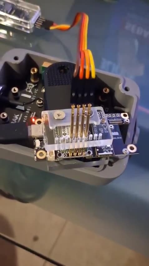
Thank you for your assistance.

Welcome to the forum @yespapa972

It usually works unless the chip is damaged.
Please share the exact log when you try to connect and flash.

Try to connect the RESET in addition, it might help to get the MCU into SWD /Jlink mode.

If the DAPlink doesn’t work with this RAK4631, try it on another RAK4631.
Check if pyOCD is on the latest version and that the nRF52 package is updated and installed as well.

Hello Bernd,

Thank you for your reply.

The RAKDAP1 is working again with this RAK4631 after a full power cycle and careful repositioning of the pogo connector.

Environment:

  • pyOCD 0.45.1 (current latest PyPI release)
  • nRF52840 built-in pyOCD target
  • RAKDAP1 DAPLink firmware 0254
  • SWD frequency: 1 MHz
  • Target powered separately by USB-C
  • GND, SWDCLK, SWDIO and VTref/3V3 connected
  • 5V not connected
  • RESET was not connected during this successful diagnostic

Successful SWD log excerpt:

AP0.IDR=0x24770011
POWER.RESETREAS=0x00000000
CORE.SP=0x2001ea90
CORE.LR=0x000a0a1d
CORE.PC=0x000a0ab0
SCB.CFSR=0x00000000
SCB.HFSR=0x00000000
SCB.DFSR=0x00000001
UICR.BOOTLOADERADDR=0x000f4000
UICR.MBRPARAMADDR=0x000fe000
UICR.PSELRESET0=0x00000012
UICR.PSELRESET1=0x00000012
UICR.NFCPINS=0xfffffffe
UICR.APPROTECT=0xffffffff
UICR.REGOUT0=0xfffffffd
SWD DIAGNOSTIC COMPLETE

The MCU resumed normally after the diagnostic.

However, the remaining problem is:

  • RESET measures about 2.12 V instead of approximately 3.3 V
  • The RAK4631 enumerates temporarily over USB as 239a:8029, then disconnects
  • Meshtastic does not answer over the serial port

The earlier failed connection log was:

pyocd.core.exceptions.TransferError:
SWD/JTAG communication failure (No ACK)

I will try connecting the RAKDAP1 RESET signal as you suggested.

Do you recommend installing a specific Nordic CMSIS device pack in addition to pyOCD’s built-in nRF52840 target?

Also, is there a known-good complete flash image specifically compatible with the RAK4631 Arduino/UF2 bootloader and Meshtastic?

Best regards

Hello Bernd,

Follow-up after testing the RAKDAP1 nRST connection:

Connect-under-reset succeeded at 1 MHz:

RESET.ASSERTED=True
AP0.IDR=0x24770011
RESET.RELEASED=False
CORE.PC=0x00000a80
SCB.CFSR=0x00000000
SCB.HFSR=0x00000000
UICR.BOOTLOADERADDR=0x000f4000
UICR.PSELRESET0=0x00000012
UICR.PSELRESET1=0x00000012
SWD UNDER-RESET DIAGNOSTIC COMPLETE

The core resumed normally. No erase, flash, recover, unlock or UICR write was performed.

Electrical results:

  • RAKDAP1 powered, nRST connected:
    3V3 = 3.32 V
    RESET after release = 2.16 V

  • RAKDAP1 powered, nRST disconnected from the target:
    3V3 = 3.32 V
    RESET = 3.15 V

  • RAK4631 powered standalone through its USB-C, with no probe or SWD wiring:
    3V3 = 3.32 V
    RESET = 2.12 V
    USB 239a:8029 enumerates, ttyACM0 appears, then disconnects after about one second.

Power-off measurements:

  • RESET to 3V3: approximately 9.9 kOhm
  • RESET to GND: approximately 177 kOhm
  • Reverse meter polarity: approximately 53.9 kOhm

The Arduino UF2 bootloader 0.4.2 and Meshtastic 2.7.26 have already been restored/flashed successfully. The CPU was observed executing the Meshtastic firmware without a HardFault.

Could the low RESET voltage when powered through USB-C indicate a known hardware issue with the reset or USB power circuitry on the WisMesh RAK19026 base board?

Would you recommend a specific complete known-good image or another electrical check?

Best regards

The reset is just a button with a 10k pull-up connected to the nRF52840 inside the RAK4630 module. The button connects the nRESET input to GND. It acts on low level, but I can’t find any specific voltage level in the nRF52840 datasheet.
As long as the MCU boots up normally after releasing the button I don’t see any problem.

Hello Bernd,

Thank you for your reply.

I connected the RAKDAP1 RESET output to the board nRESET pin, in addition to SWDIO, SWCLK, GND and 3V3. The target is powered separately through USB-C. The RAKDAP1 5V pin is not connected.

The board is a RAK19026 revision VA with an integrated RAK4630.

pyOCD version: 0.45.1
Target: nRF52840

Connect-under-reset now succeeds. No flash, erase, recover, unlock or UICR write was performed.

Relevant log:

RESET.ASSERTED=True
AP0.IDR=0x24770011
DHCSR.UNDER_RESET=0x03050000
DEMCR.ORIGINAL=0x00000000
RESET.RELEASED=False
DHCSR.VECTOR_CATCH=0x02030003
POWER.RESETREAS=0x00000004
CORE.SP=0x20000400
CORE.PC=0x00000a80
CORE.xPSR=0x01000000
SCB.CFSR=0x00000000
SCB.HFSR=0x00000000
APP.RESET_VECTOR=0x000a0c91
BOOT.RESET_VECTOR=0x000fb129
UICR.BOOTLOADERADDR=0x000f4000
UICR.MBRPARAMADDR=0x000fe000
UICR.PSELRESET0=0x00000012
UICR.PSELRESET1=0x00000012
UICR.NFCPINS=0xfffffffe
UICR.APPROTECT=0xffffffff
UICR.REGOUT0=0xfffffffd
DHCSR.RESUMED=0x01050001
SWD UNDER-RESET DIAGNOSTIC COMPLETE

“RESET.RELEASED=False” means that the probe reports RESET is no longer asserted.

After releasing RESET and resuming the CPU, the target still does not enumerate over USB. During a 15-second observation, neither Meshtastic USB ID 239a:8029 nor bootloader ID 239a:0029 appeared.

Previously, when powered from USB-C without the debugger, the target sometimes appeared for approximately one second and then disconnected. The measured nRESET voltage after release was approximately 2.12 V, while 3V3 was 3.32 V. The resistance between nRESET and 3V3 with power removed was approximately 9.9 kΩ.

Since SWD connect-under-reset works and the CPU resumes without CFSR/HFSR faults, what exact next check do you recommend before attempting any further flash operation?

Also, can you confirm whether the RAKDAP1 pin labelled 3V3 is an output supply or only a target-voltage reference/input?

Best regards

Important correction to my previous message:

The separate wire between the RAKDAP1 RESET output and the board nRESET pin was accidentally not physically connected during this test.

Therefore, although the log reports RESET.ASSERTED=True, this only represents the probe output state. The target itself was not physically held under reset, so this log must not be considered a valid connect-under-reset test.

The SWD connection, register reads and CPU resume did succeed, but without the nRESET connection.

Sorry for the incorrect wiring description. I will not repeat the test until the nRESET wire is explicitly connected and verified.

Hello Bernd,

I have now repeated the test with the separate nRESET wire physically connected between the RAKDAP1 RESET output and the RAK19026 VA nRESET pin.

This is the valid connect-under-reset result:

RESET.ASSERTED=True
AP0.IDR=0x24770011
DHCSR.UNDER_RESET=0x03010000
DEMCR.ORIGINAL=0x00000000
RESET.RELEASED=False
DHCSR.VECTOR_CATCH=0x02030003
POWER.RESETREAS=0x00000005
CORE.SP=0x20000400
CORE.PC=0x00000a80
CORE.xPSR=0x01000000
SCB.CFSR=0x00000000
SCB.HFSR=0x00000000
APP.RESET_VECTOR=0x000a0c91
BOOT.RESET_VECTOR=0x000fb129
UICR.BOOTLOADERADDR=0x000f4000
UICR.MBRPARAMADDR=0x000fe000
UICR.PSELRESET0=0x00000012
UICR.PSELRESET1=0x00000012
UICR.NFCPINS=0xfffffffe
UICR.APPROTECT=0xffffffff
UICR.REGOUT0=0xfffffffd
DHCSR.RESUMED=0x01010001
SWD UNDER-RESET DIAGNOSTIC COMPLETE

“RESET.RELEASED=False” means the probe reports that RESET is no longer asserted.

RESETREAS=0x00000005 now includes the RESETPIN bit, confirming that the physical nRESET connection was effective.

The CPU was captured at the reset vector, no CFSR or HFSR fault was present, RESET was released and the CPU resumed successfully.

No flash, erase, recover, unlock or UICR write was performed.

However, the Meshtastic USB interface still does not remain available after startup. What would you recommend as the next diagnostic or recovery step?

Best regards

What exact firmware are you flashing?

There are three parts required.

  1. Bootloader
  2. Softdevice
  3. Firmware

Usually you only flash the Firmware and leave the Bootloader and Softdevice untouched.
In your case it might be that the Bootloader or Softdevice was erased, which means the device will not even start the firmware. Nor will double push reset for UF2 bootloader or anything else work.

I am guessing (you never mentioned it), that you are using the version of the RAK4631 with the Arduino bootloader.
In this case you can use the attached HEX file to restore the module.
This is the flash image used in our production. It includes the bootloader, softdevice and a test firmware.

WisBlock_SENS_V2.0.0_2023.11.02.09.57.38+Bootloader.hex (2.4 MB)

Hello Bernd,

Thank you for the clarification and for providing the production HEX image.

The hardware is a RAK19026 revision VA with an integrated RAK4630. It is using the Arduino/UF2 bootloader, confirmed through INFO_UF2.TXT.

The exact software currently installed is:

  • RAKWireless Arduino/UF2 bootloader 0.4.2
  • SoftDevice S140 6.1.1
  • Official Meshtastic firmware v2.7.26.54e0d8d for RAK4631

Before installing Meshtastic, the complete 1 MiB internal flash was restored and verified by a full readback. The six required UICR words were also restored and read back successfully.

After flashing Meshtastic, the device was seen briefly as USB VID:PID 239a:8029, but it disconnects after approximately one second or sometimes does not enumerate at all.

A real connect-under-reset test was then performed with nRST physically connected:

  • AP0.IDR = 0x24770011
  • RESETREAS = 0x00000005
  • PC captured at 0x00000A80
  • CFSR = 0
  • HFSR = 0
  • RESET released successfully
  • Core resumed: DHCSR = 0x01010001

No flash, erase, recover, unlock or UICR change was performed during that test.

I have audited the attached file:

WisBlock_SENS_V2.0.0_2023.11.02.09.57.38+Bootloader.hex
SHA-256:
1d5e6d0b2f0e33e9975bd1d61e718188435b4a2e80007ace197dcb602f243e97

It is a valid complete image containing the MBR, S140 6.1.1 SoftDevice, RAK-SENS production test firmware, UF2 bootloader 0.4.3, bootloader settings and the complete UICR.

The MBR and SoftDevice in this image are byte-for-byte identical to those already restored on the board. Its six non-erased UICR words are also identical to the original UICR backup and to the values currently restored.

Therefore, flashing this image would mainly replace Meshtastic with the RAK-SENS production test application and update the bootloader from 0.4.2 to 0.4.3.

I have not flashed the attached image yet.

Given these verified facts, do you still recommend flashing this complete production image as a controlled test to determine whether USB remains stable with the RAK factory test firmware?

If yes, please also confirm whether you recommend a full chip erase followed by flashing the complete HEX through RAKDAP1/pyOCD, or another specific procedure.

Best regards,
Alain

I do not know what Meshtastic firmware is doing, I only know that quite often a messed up setting caused a device with Meshtastic firmware to behave erratic.

With our production firmware, I know at least what it is doing and where I can start debugging if something goes wrong.

A full chip erase is always a good idea, specially when firmware saves some settings in a Flash area that is not erased by flashing a new firmware.

Thank you, Bernd. I understand that you recommend a full chip erase followed by the complete RAK production image, so that Meshtastic and any persistent settings are removed from the test.

For completeness, an ERASEALL was already performed earlier. I then restored and read-verified the MBR, S140 6.1.1, UF2 bootloader 0.4.2, Meshtastic 2.7.26 and the original UICR values. The remaining symptom is still RESET at about 2.12 V and USB enumeration for approximately one second.

I can nevertheless perform the production-firmware test as a controlled A/B test. Could you please confirm:

  1. that the supplied WisBlock_SENS_V2.0.0_2023.11.02.09.57.38+Bootloader.hex is correct for the RAK19026 VA with integrated RAK4630;
  2. the exact pyOCD erase and flash commands you recommend with the RAKDAP1;
  3. whether the supplied HEX contains everything required after a full chip erase, including UICR.

I will not perform the erase or flash until these points are confirmed.

  1. See (3)
  2. pyocd erase -t nrf52840 --chip
  3. WisBlock_SENS_V2.0.0_2023.11.02.09.57.38+Bootloader.hex is three years old, better to use rak4361-arduino.hex which is updated with the latest bootloader.

Thanks Bernd. Before performing the full chip erase, could you please confirm whether rak4361-arduino.hex is the exact filename, or whether you meant rak4631-arduino.hex?

Is this file one of the three attachments?

Could you also confirm the complete sequence you recommend:

pyocd erase -t nrf52840 --chip
pyocd flash -t nrf52840 <confirmed-file>.hex

Does this HEX contain the SoftDevice, the latest Arduino/UF2 bootloader, the application and the required UICR settings?

The hardware is a RAK19026 VA with an integrated RAK4630. After recovery, I intend to reinstall Meshtastic through UF2.

English is not my first language, but your sentence doesn’t make any sense.

Just download the file rak4631-arduino.hex from the link provided and use it.

rak4631-arduino.hex includes everything needed to run the MCU, bootloader, softdevice and an application. It runs independent of the used Base Board, it doesn’t matter if you use a RAK19003, a RAK19007, a RAK19026 or a custom PCB.

Thanks Bernd. We performed the full-chip erase and programmed the complete rak4631-arduino.hex image.

Because normal pyOCD target discovery remained unstable, the main flash was programmed through direct NVMC access at 250 kHz, word by word. The complete 1 MiB flash was then read back and verified:

Expected/read-back SHA-256:
f4a8667ea7f5672b69cde29c99044868979cd915ca44bca54cf73bfeb4b22011

The UICR was not modified and its six relevant values remain correct. The application and bootloader vectors were also verified.

After a complete power cycle, with the RAKDAP1 and SWD wiring completely removed, the board still does not enumerate on USB. Measurements with the RAK19026 powered only through USB-C are:

3V3 = 3.32 V
RESET = 2.12 V

This is exactly the same RESET voltage and USB symptom previously observed with Meshtastic. Could you please advise which component or test point in the RAK19026 VA RESET circuit should be checked next?

I never needed to change anything like UICR or use NVMC when flashing a RAK4630 over JLink or DAPLink.
I am not sure why you are messing around with these things.

What always works for me is to do a chip erase and then flash bootloader/softdevice and application.
If that doesn’t work on your module, it could be a hardware problem or you messed something seriously up in the module.