I am developing a custom PCB using RAK4631 module, and I’ve made a PCB footprint to connect the module. The only thing I’m worried about the footprint is the 40pin female connector.
Question 1
I need to know whether my connector selection mates RAK4671 properly or not.
Also, I’m looking for the Press-Fit standoffs for the same. The provided part numbers in the documentation are out of stock, so I need an alternate part no. that matches the module.
Question 2
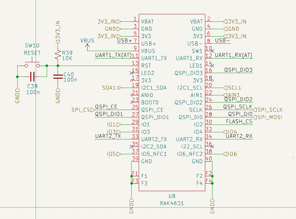
I’m planning to run the RAK4631 with 3.3V. So, if I keep my VBAT pin (1,2) unconnected and only apply +3.3V to pin5 and pin6, will it run OK? Or do I need to provide +3.3V to the VBAT pins as well?
I don’t know how far you already are down this pathway.
If you have the available space, an alternative approach is to make a custom PCB that supports the WisBlock baseboard of your choice. You get the advantages of all the supporting circuit, like USB comms and charging and you can pick a baseboard according to whether you need sensor slots or IO slots.
I use the 19007 base, packed out with all sensor slots in use and an SD card carrier in the IO slot. The 3 4-way headers on that baseboard are plugged into my custom PCB so that I can talk to an additional serial device (rx/tx), I2C device (SCL/SDA), as well as export IO1 and IO2 and connect to a very large battery (BAT). My custom board then has mounting holes that correspond to where I need them rather than the footprint of the 19007.
If you use a RAK4631, you need to apply VBAT, as it is used.
If you want to do a single supply setup, you should connect it to 3.3V, don’t leave it open.
@psupine thanks for the reply, that is not my use case here, I’m trying to build something from scratch, and I only want to use RAK4731 as the controller.
@beegee thank you for clarifying the power section and the standoff link.
I looked for the TXGA connector on LCSC, but they are unavailable there. Can you provide the part number of the Panasonic-compatible one?
Hi,
Sorry for the late reply, actually I’m doing two iterations, one with RAK4630 bare module and the second one with RAK4631, the main purpose of using RAK4631 is to take advantage of interchangeability and easy replacement.
Got one more question regarding the power section.