RAK4631 + RAK5802 in Zephyr

I’m interested in connecting a device to a combination of RAK4631 and RAK5802 using RS485 interface.

I write the code in the Zephyr environment and I cant seem to make it work.

Here is the source code (main.c):

#include <zephyr/drivers/gpio.h>
#include <zephyr/kernel.h>
#include <zephyr/device.h>
#include <zephyr/drivers/uart.h>

// chip used in the RS485 module:
//   http://file.3peakic.com.cn:8080/product/Datasheet_TP8485E.pdf

// RAK4631 Schematics:
//   https://images.docs.rakwireless.com/wisblock/rak4631/datasheet/schematic.png

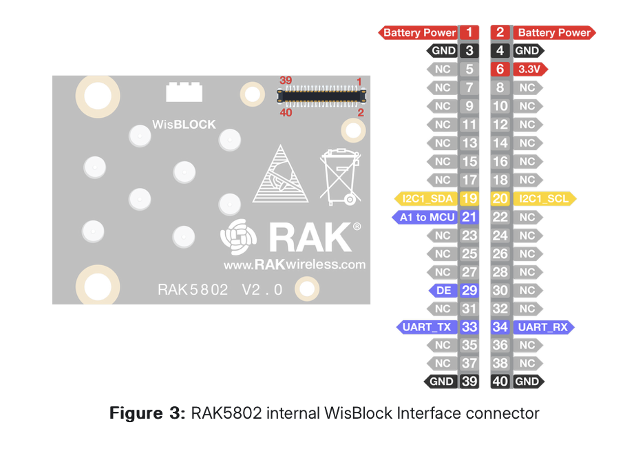
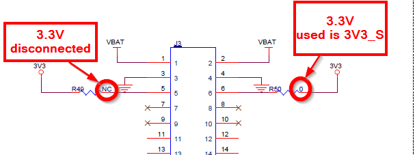
// RAK5802 Schmatics:
//   https://images.docs.rakwireless.com/wisblock/rak5802/datasheet/schematic.png

// Example Arduio code:
//   https://github.com/RAKWireless/WisBlock/tree/master/examples/RAK4630/IO/RAK5802_RS485

// RAK4631 UART connected to RS485 module
#define RS485 DEVICE_DT_GET(DT_CHOSEN(uart_rs485))

static const struct device *rs485 = RS485;

static void configure_uicr(void) {
  if ((NRF_UICR->REGOUT0 & UICR_REGOUT0_VOUT_Msk) != (UICR_REGOUT0_VOUT_3V3 << UICR_REGOUT0_VOUT_Pos)) {
    NRF_NVMC->CONFIG = NVMC_CONFIG_WEN_Wen;
    while (NRF_NVMC->READY == NVMC_READY_READY_Busy) {}

    NRF_UICR->REGOUT0 =
        (NRF_UICR->REGOUT0 & ~((uint32_t)UICR_REGOUT0_VOUT_Msk)) |
        (UICR_REGOUT0_VOUT_3V3 << UICR_REGOUT0_VOUT_Pos);

    NRF_NVMC->CONFIG = NVMC_CONFIG_WEN_Ren;
    while (NRF_NVMC->READY == NVMC_READY_READY_Busy) {}

    // System reset is needed to update UICR registers.
    NVIC_SystemReset();
  }
}

int main(void) {
  uint8_t ch = 1;
  int ret;

  printk("** Starting\n");

  // am not sure if I need this or not (?)
  configure_uicr();

  // echo loop
  while (true) {
    // poll for input
    if ((ret = uart_poll_in(rs485, &ch)) == 0) {
      // print what we've got
      printk("> 0x%02x\n", ch);
      
      // echo back to peer
      uart_poll_out(rs485, ch);
    
    } else if (ret < -1) {
      printk("EE Error polling in: %d\n", ret);
      k_sleep(K_SECONDS(1));
    }

    // sleep for 1 ms just for funzies
    k_sleep(K_MSEC(1));
  }
  
  return 0;
}

Here is the project configuration file (prj.conf):

CONFIG_STDOUT_CONSOLE=y
CONFIG_USB_CDC_ACM=y
CONFIG_USB_DEVICE_STACK=y
CONFIG_USB_DEVICE_PRODUCT="RAK4631 Zephyr"
CONFIG_USB_DEVICE_MANUFACTURER="RAKwireless"
CONFIG_USB_DEVICE_VID=0x1915
CONFIG_USB_DEVICE_PID=0x5300
CONFIG_USB_DEVICE_INITIALIZE_AT_BOOT=y
CONFIG_UART_LINE_CTRL=y

# We need to control GPIO pins
CONFIG_GPIO=y

# We need to work with a UART (connected to RS485)
CONFIG_SERIAL=y

Here is the overlay file (rak4631_nrf52840.overlay):

/ {
	chosen {
		/delete-property/ zephyr,uart-mcumgr;
		/* uart1 is used by RS485. */
		/delete-property/ zephyr,bt-mon-uart;
		/delete-property/ zephyr,bt-c2h-uart;

		uart,rs485 = &uart1;
		zephyr,console = &cdc_acm_uart0;
	};
};

&uart1 {
	current-speed = <57600>;
	compatible = "nordic,nrf-uarte";
	status = "okay";

	tp8485e: tp8485e {
		compatible = "tp8485e";
		enable-gpios = <&gpio0 17 GPIO_ACTIVE_HIGH>;
		status = "okay";
	};
};

&zephyr_udc0 {
	cdc_acm_uart0: cdc_acm_uart0 {
		compatible = "zephyr,cdc-acm-uart";
	};
};

I build (with “west build -p always -b rak4631/nrf52840 .” in the app folder)
… and flash (with “west flash”)
… and open a serial terminal to an RS485 dongle I have connected to my desktop (I tested it and it works with other RS485 devices)
… and nothing I type in my terminal makes it through … as if the RAK4631 doesnt get the input.

When I change the code to only write to the UART (loop of only “uart_poll_out()”) I see nothing in the serial terminal.

Some of the code I used in the overlay file was borrowed from:

What am I missing here ? why cant I make this RS485 module to work ?

Hello @Oberon,

Firstly configure_uicr() must be called. If the rak4631 board is powered over USB, 1.8 volts is default and that is not enough to turn the LEDs on.

Please try to use 9600 baudrate as current-speed. Also, you must control the de pin. You can use following code to control de pin.

#define UART_DEVICE_NODE DT_CHOSEN(uart_rs485)
static const struct device *const uart_dev = DEVICE_DT_GET(UART_DEVICE_NODE);

#define DE_PIN 17
static const struct device *port0 = DEVICE_DT_GET(DT_NODELABEL(gpio0)); 

void print_uart(char *buf)
{
	int msg_len = strlen(buf);

	for (int i = 0; i < msg_len; i++) {
		uart_poll_out(uart_dev, buf[i]);
	}
}

int main(void)
{
#if defined(CONFIG_BOARD_RAK4631)
	configure_uicr();
#endif

	if (!device_is_ready(uart_dev)) {
		printk("UART device not found!");
		return 0;
	}

	int err = gpio_pin_configure(port0, DE_PIN, GPIO_ACTIVE_LOW);
	if (err < 0) {
		printk("DE_PIN init error\n");
	}

	printk("RS485 Example! %s\n", CONFIG_BOARD);


	while (1) {
		gpio_pin_set(port0, DE_PIN, 1);
		print_uart("Hello!");
		gpio_pin_set(port0, DE_PIN, 0);

		k_sleep(K_MSEC(1000));
	}

	return 0;
}

Best regards,
Sercan.

Why do you set DE_PIN back to 0 ?

The aim is to begin and end transmission. You can configure it according to your use case. By the way, if you want to use enable-gpios property, you must set it as GPIO_ACTIVE_LOW like I do. Probably, zephyr driver will set and clear DE_PIN automatically. However, I am not totally sure. Please be aware about this.

In the RAK5802 schematics it is marked as not connected ?! (IO1 - DE_PIN)
Is it needed to be set to 0 in order to receive ?

In the schematics R63 which is connected to TCON which is connected to IO1 which is connected to P0.17 is marked as NC ( = not connected)

Besides, aren’t you supposed to power the device with IO2 ?
This code doesn’t work

According to schematic, you are right. There is no need to control DE pin.


This diagram causes confusion.

I do not have RAK5802 on my side, so I am not able to test it. Is decreasing uart speed/baudrate solved your problem? Or, it stops working if you remove de pin config.

The example code works (once I change the baud to 57600, the device I connect to is rated to work in 57600 baud).

Your C code you wrote eariler doesnt, I assume it is because you never set the value of IO2 which is needed to power 3V3_S ?

Please check with this code.

#include <stdio.h>
#include <zephyr/kernel.h>
#include <zephyr/drivers/gpio.h>
#include <zephyr/drivers/uart.h>

#include <zephyr/logging/log.h>
LOG_MODULE_REGISTER(main, LOG_LEVEL_DBG);

/* change this to any other UART peripheral if desired */
#define UART_DEVICE_NODE DT_CHOSEN(uart_rs485)
static const struct device *const uart_dev = DEVICE_DT_GET(UART_DEVICE_NODE);

#define DE_PIN 2
static const struct device *p1 = DEVICE_DT_GET(DT_NODELABEL(gpio1));

#if defined(CONFIG_BOARD_RAK4631)
static void configure_uicr(void) {
	if ((NRF_UICR->REGOUT0 & UICR_REGOUT0_VOUT_Msk) !=
		(UICR_REGOUT0_VOUT_3V3 << UICR_REGOUT0_VOUT_Pos)) {
		NRF_NVMC->CONFIG = NVMC_CONFIG_WEN_Wen;
		while (NRF_NVMC->READY == NVMC_READY_READY_Busy){}

		NRF_UICR->REGOUT0 = (NRF_UICR->REGOUT0 & ~((uint32_t)UICR_REGOUT0_VOUT_Msk)) |
							(UICR_REGOUT0_VOUT_3V3 << UICR_REGOUT0_VOUT_Pos);

		NRF_NVMC->CONFIG = NVMC_CONFIG_WEN_Ren;
		while (NRF_NVMC->READY == NVMC_READY_READY_Busy){}

		LOG_INF("REGOUT0 is updated!");

		// System reset is needed to update UICR registers.
		NVIC_SystemReset();
	}
}
#endif

/*
 * Print a null-terminated string character by character to the UART interface
 */
void print_uart(char *buf)
{
	int msg_len = strlen(buf);

	for (int i = 0; i < msg_len; i++) {
		uart_poll_out(uart_dev, buf[i]);
	}
}

int main(void)
{
#if defined(CONFIG_BOARD_RAK4631)
	configure_uicr();
#endif

	if (!device_is_ready(uart_dev)) {
		printk("UART device not found!");
		return 0;
	}

	int err = gpio_pin_configure(p1, DE_PIN, GPIO_ACTIVE_LOW);
	if (err < 0) {
		printk("DE_PIN init error\n");
	}

	printk("RS485 Example! %s\n", CONFIG_BOARD);


	while (1) {
		/* IO2 HIGH  3V3_S ON */
		gpio_pin_set(p1, DE_PIN, 1);
		k_sleep(K_MSEC(300));

		print_uart("Hello!");

		/* IO2 LOW  3V3_S OFF */
		gpio_pin_set(p1, DE_PIN, 0);
		k_sleep(K_MSEC(300));

		k_sleep(K_MSEC(1000));
	}

	return 0;
}

This is doing what Arduino code does. Tomorrow, I will talk with the HW team to identify the confusion.

I tested with “enable-gpios = <&gpio1 2 GPIO_ACTIVE_HIGH>;” in the overlay file and it seems to work.
Please update the schematics, they are misleading.

Thanks for your help

image

3V3_S which is switched module on and off with WB_IO2 (P1.02). There is no need to control DE (WB_IO1 - P0.27) pin. It is controlled by the status of the UART TX line. I hope this explanation clears up the confusion.

This topic was automatically closed 10 days after the last reply. New replies are no longer allowed.