
Hi,
I have a RAK4631 Arduino version LoRa end node with me, due to some space constrains and low power application I am forced not to use any baseboard. I need your guidance and support to connect RAK4631 to TTL module so that I can program or debug my module and how do I power up my module do you have any documentation supporting my query?
Thank You,
Divya M
Hello Divya,
You can use the schematics of the BaseBoards and of the RAK4631 to understand the power supply requirements.
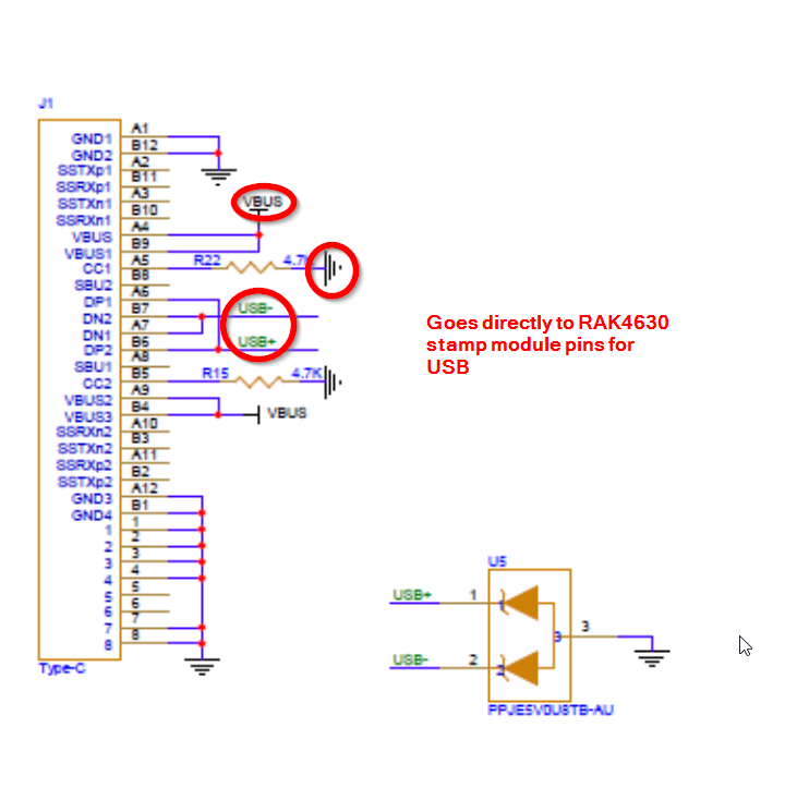
The RAK4631 (nRF52840 inside) is not using the UART to communicate, it is using it’s internal USB. Basically you connect the USB+/USB-, VUSB and GND of the RAK4631 to a USB connector and go directly to your computer. To be safe there should be some protection circuit, that is implemented on the BaseBoards as well.
But in your case, I would switch from the WisBlock Core RAK4631 and use instead the WisDuo RAK4630 Stamp module and implement that on your own PCB.
USB connection (taken from RAK19007
RAK4631 power supply (taken from RAK4631 datasheet
Hi Beegee,
In this case can I use the libraries and steps used in the software section of RAK4631 documentation centre.
Thankyou,
Divya M
Yes, you can use them.
However the RAK4630 Stampmodule comes by default with the RUI3 AT command firmware that is using a different bootloader.
But you can change the RAK4630 to use the open-source bootloader (and all the usual Arduino libraries).
The guide for changing is in our Documentation Center
LoRa module’s maximum supply voltage is 3.3 but from my TTL module I derive 5v as output so I should step it down and then proceed?
Yes, you need to use a regulator.
Input for VBAT is 3.6 to 4.2V, 3V3 is obviously 3.3V.
The RAK4630 works in lowest power consumption when VBAT is in above range and above the 3V3 supply.
You can supply both VBAT and 3V3 with 3.3V but the power consumption might be higher.
The reason is that the nRF52 is using its own DC/DC converter from VBAT, while 3V3 supplies the SX1262
Hi,
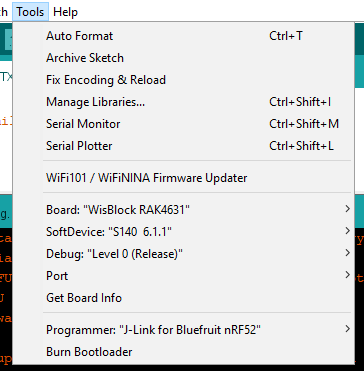
After following all of the steps above, I tried uploading the example code into it. I ended up getting this error.
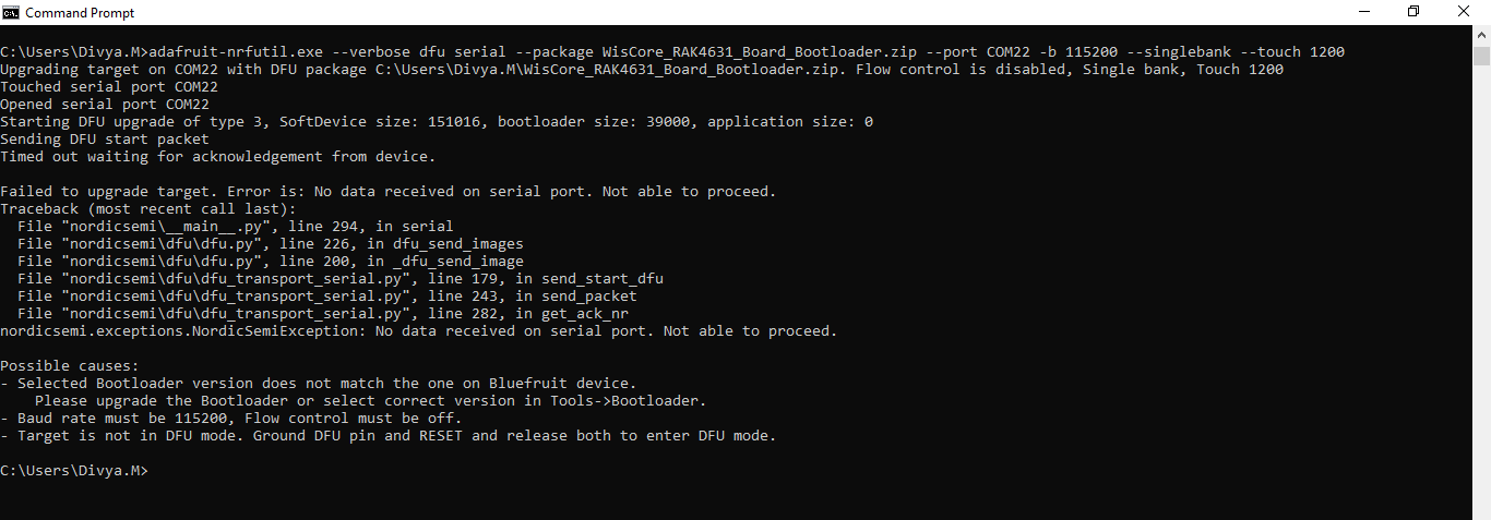
Opened serial port COM22
Starting DFU upgrade of type 4, SoftDevice size: 0, bootloader size: 0, application size: 66504
Sending DFU start packet
Timed out waiting for acknowledgement from device.

Failed to upgrade target. Error is: No data received on serial port. Not able to proceed.
Traceback (most recent call last):
  File "__main__.py", line 296, in serial
  File "dfu\dfu.py", line 235, in dfu_send_images
  File "dfu\dfu.py", line 199, in _dfu_send_image
  File "dfu\dfu_transport_serial.py", line 179, in send_start_dfu
  File "dfu\dfu_transport_serial.py", line 243, in send_packet
  File "dfu\dfu_transport_serial.py", line 282, in get_ack_nr
nordicsemi.exceptions.NordicSemiException: No data received on serial port. Not able to proceed.

Possible causes:
- Selected Bootloader version does not match the one on Bluefruit device.
    Please upgrade the Bootloader or select correct version in Tools->Bootloader.
- Baud rate must be 115200, Flow control must be off.
- Target is not in DFU mode. Ground DFU pin and RESET and release both to enter DFU mode.
I have also attached the screenshot of the tools setting in my Arduino IDE
Thankyou
So you are using now the RAK4630 stamp module.
Was the change to Arduino Bootloader successful?
Does the device show up as USB port when you plug it in?
If it is detected as COM port, how does it show up?
Mine is a Arduino version RAK4631 module
Ok, you have at least the Arduino Bootloader.
If you force a double reset (not sure if you have a button implemented), does the device show up as an external drive with the name RAK4631?
If that works, try to upload the firmware after the device is in that status.
Check the COM port number, it is a different COM port than usual.
I implemented a button and tried double reset, but still I don’t find the device shown up as an external drive with the name RAK4631
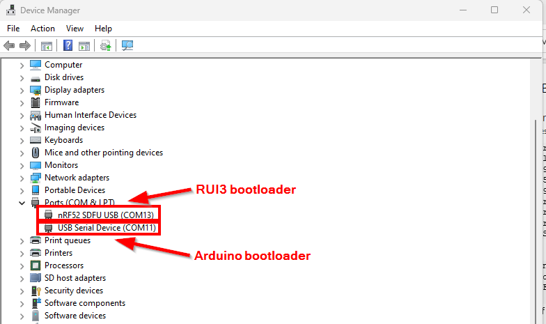
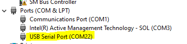
Note: Even when I disconnect the RAK4631 from the TTL and only connect the TTL to my PC, I see the USB Serial Port (COM22) in the device manager
With TTL you mean you use the UART port of the RAK4630 to connect to an UART/USB converter and then to the computer?
That doesn’t work.
The RAK4630 can be only flashed over it’s USB connection.
Did you connect the USB as I showed here:
https://forum.rakwireless.com/uploads/default/original/2X/4/4909517c58fc8957aadeb6bf673c0be1ff5a7df4.png
From there you connect to your computer.
I connected the USB+ and USB- of RAK4631 to the Tx Rx of the USB to UART module (TTL) where the USB of TTL goes to the computer’s USB port for debugging and the Tx Rx to RAK4631
There is no need for a USB to UART adapter.
USB+ goes to USB+ of the computer
USB- goes to USB- of the computer
VUSB goes to VUSB of the computer
GND goes to GND of the computer
Hi,
I tried the same way, still my device is not responding. Tried to update the bootloader ended up with the same error as I got in the IDE
Thank you.
Is the device showing as a USB COM port?
Are you sure it is COM22?
If your device has RUI3, you have to use the nrfutil.exe tool. Not the adafruit-nrfutil.exe tool.
Now I see a new problem, RAK4631 is not detected as a COM port in device manager

Servus @beegee. I hope I am not too late to participate in this discussion.
I am in the same situation as @DivyaM. I am developing my own board for my Meshtastic solar repeater. In my case I’ll do all the energy harvesting and management of the accumulators externally (Solar panel + MPPT charger+ supercapacitors + DC-DC converters).
I have now come to the point where I need to power up the RAK4631 and there are a few things regarding the power supply that are still not clear to me.
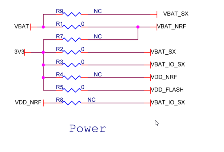
First I thought that it would be enough to supply 3.3V directly to the pin available where the SWD port is, but based on all the provided documentation in different threads of the forum and after inspecting RAK19007 and RAK4631 schematics, that does not seem to be enough to power up the nRF52 microcontroller that is embedded in the RAK4630/31.
It is my understanding that the nRF52 comes with an embedded DC-DC buck converter that outputs VDD_NRF=3.3V that is then used to energise ** itself**(is this correct?) and other RAK modules (but NOT the SX1262).
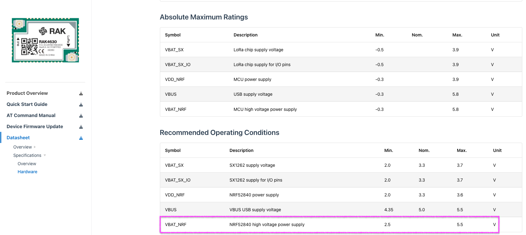
Regarding the max allowed operating value for VBAT_NRF I see that it supports up to 5.5V so, in my case I am going to use a buck-boost converter that takes the variable voltage seen on my supercap and converts it to constant 5V to feed VBAT_NRF. Is this a valid approach?
The SX1262 on the other hand, needs a “cleaner” 3.3V power supply to work which is completely different from the other 3.3V seen on VDD_NRF.
This “cleaner” 3.3V used to power the SX1262 chip is coming from the output of the SGM6035-ADJ present in the RAK19007. Is my interpretation correct?
If so, then I would only need to feed the RAK4631 with the output of my buck-boost (5V) to VBAT_NRF (Pins 1 and 2 of the 40-pin connector) and another cleaner 3.3V to Pins 5 and 6.
I apologise in advance if this post was a bit too long.
Kind regards.
Milton
(1) Correct, the nRF52 has its own DC/DC and it is enabled in the RAK4630.
(2) VBAT_NRF < 5.5V is correct
(3) Supply for the SX1262, see my proposal below
If you want to use the RAK4631 Core module without the base board, you still have to supply through the 40 pin connector on the bottom. You cannot supply through the 3.3V of the SWD header. The Core module is designed to have 3V3 and VBat supply. You would have to remove/solder resistors on the Wisblock Core PCB.
If you want to go without the base board, you might be better off with the RAK4630 stamp module.
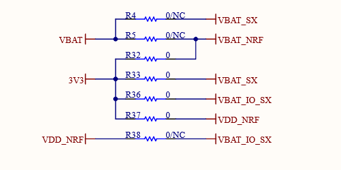
You can do a single supply voltage to the stamp module following this connection on the stamp module:
VBAT_NRF, VBAT_SX, VBAT_IO_SX and VDD_NRF connected to your 3.3V supply:
This is used in our RAK10702 Indoor Air Quality device and in our RAK2560 SensorHub.
Thanks for the reply.
The reason behind using the RAK4631 and not RAK 4630 module is because I would like to use the base board only to flash and configure the Core module. After that I would remove the 4631 and place it on my custom board where I am also going to place the 40 pin connector.
You cannot supply through the 3.3V of the SWD header.
Thanks, for clarifying this.
So if I understood correctly, there shouldn’t be a need to solder or desolder any resistor from from RAK4631 as long as I supply the two voltages (VBAT_NRF < 5.5V and a clean 3.3V) through the 40 pin connector, right?
If you want to use the RAK4631 Core module without the base board, you still have to supply through the 40 pin connector on the bottom.
Can you confirm that Pins 5 and 6 are the ones used to supply 3.3V to the SX1262?
Now regarding current consumption, which one consumes the lowest? RAK4630 or RAK4631?
Thanks