So you are using now the RAK4630 stamp module.
Was the change to Arduino Bootloader successful?
Does the device show up as USB port when you plug it in?
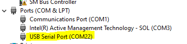
If it is detected as COM port, how does it show up?
So you are using now the RAK4630 stamp module.
Was the change to Arduino Bootloader successful?
Does the device show up as USB port when you plug it in?
If it is detected as COM port, how does it show up?
Mine is a Arduino version RAK4631 module
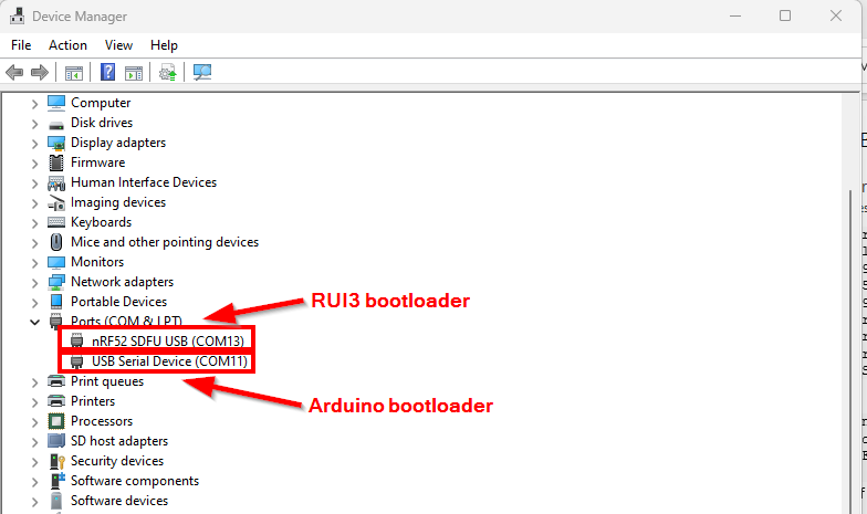
Ok, you have at least the Arduino Bootloader.
If you force a double reset (not sure if you have a button implemented), does the device show up as an external drive with the name RAK4631?
If that works, try to upload the firmware after the device is in that status.
Check the COM port number, it is a different COM port than usual.
I implemented a button and tried double reset, but still I don’t find the device shown up as an external drive with the name RAK4631
Note: Even when I disconnect the RAK4631 from the TTL and only connect the TTL to my PC, I see the USB Serial Port (COM22) in the device manager
With TTL you mean you use the UART port of the RAK4630 to connect to an UART/USB converter and then to the computer?
That doesn’t work.
The RAK4630 can be only flashed over it’s USB connection.
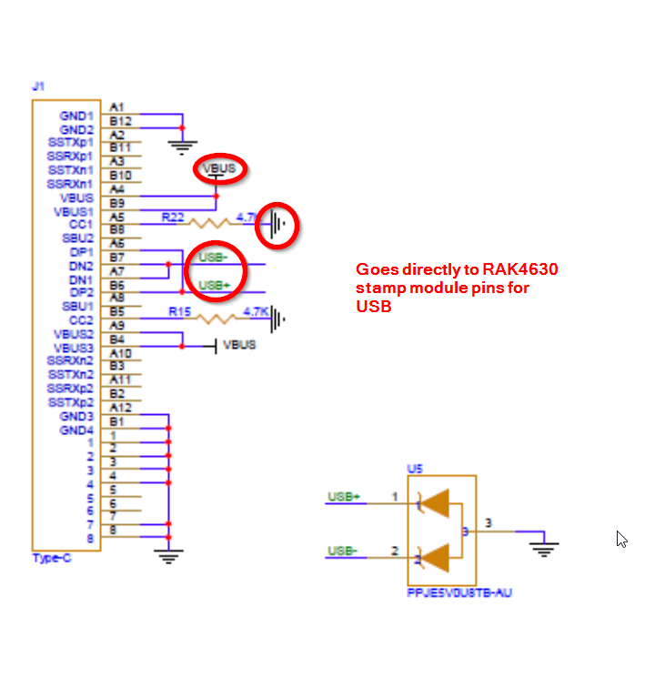
Did you connect the USB as I showed here:
https://forum.rakwireless.com/uploads/default/original/2X/4/4909517c58fc8957aadeb6bf673c0be1ff5a7df4.png
From there you connect to your computer.
I connected the USB+ and USB- of RAK4631 to the Tx Rx of the USB to UART module (TTL) where the USB of TTL goes to the computer’s USB port for debugging and the Tx Rx to RAK4631
There is no need for a USB to UART adapter.
USB+ goes to USB+ of the computer
USB- goes to USB- of the computer
VUSB goes to VUSB of the computer
GND goes to GND of the computer
Hi,
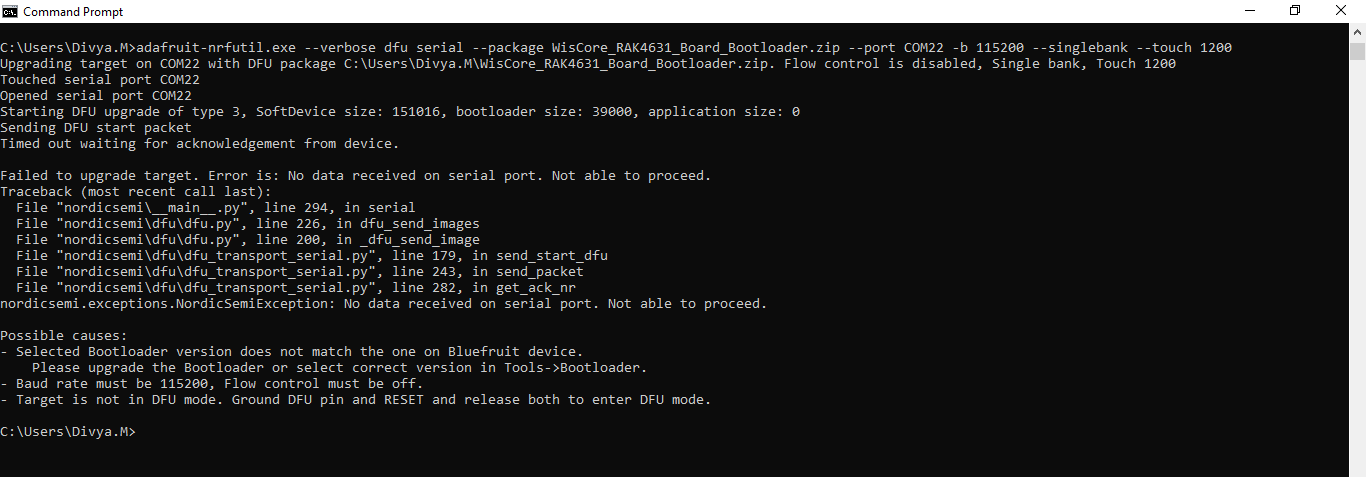
I tried the same way, still my device is not responding. Tried to update the bootloader ended up with the same error as I got in the IDE
Thank you.
Is the device showing as a USB COM port?
Are you sure it is COM22?
If your device has RUI3, you have to use the nrfutil.exe tool. Not the adafruit-nrfutil.exe tool.
Now I see a new problem, RAK4631 is not detected as a COM port in device manager

Servus @beegee. I hope I am not too late to participate in this discussion.
I am in the same situation as @DivyaM. I am developing my own board for my Meshtastic solar repeater. In my case I’ll do all the energy harvesting and management of the accumulators externally (Solar panel + MPPT charger+ supercapacitors + DC-DC converters).
I have now come to the point where I need to power up the RAK4631 and there are a few things regarding the power supply that are still not clear to me.
First I thought that it would be enough to supply 3.3V directly to the pin available where the SWD port is, but based on all the provided documentation in different threads of the forum and after inspecting RAK19007 and RAK4631 schematics, that does not seem to be enough to power up the nRF52 microcontroller that is embedded in the RAK4630/31.
It is my understanding that the nRF52 comes with an embedded DC-DC buck converter that outputs VDD_NRF=3.3V that is then used to energise ** itself**(is this correct?) and other RAK modules (but NOT the SX1262).
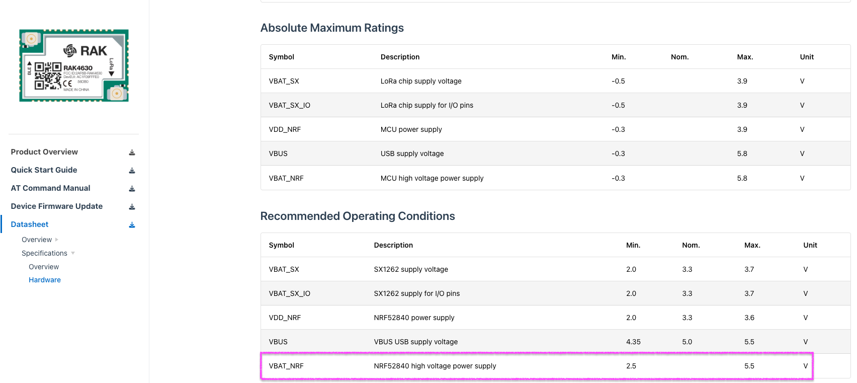
Regarding the max allowed operating value for VBAT_NRF I see that it supports up to 5.5V so, in my case I am going to use a buck-boost converter that takes the variable voltage seen on my supercap and converts it to constant 5V to feed VBAT_NRF. Is this a valid approach?
The SX1262 on the other hand, needs a “cleaner” 3.3V power supply to work which is completely different from the other 3.3V seen on VDD_NRF.
This “cleaner” 3.3V used to power the SX1262 chip is coming from the output of the SGM6035-ADJ present in the RAK19007. Is my interpretation correct?
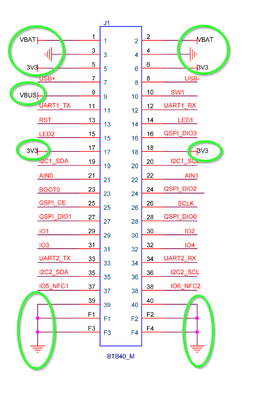
If so, then I would only need to feed the RAK4631 with the output of my buck-boost (5V) to VBAT_NRF (Pins 1 and 2 of the 40-pin connector) and another cleaner 3.3V to Pins 5 and 6.
I apologise in advance if this post was a bit too long.
Kind regards.
Milton
(1) Correct, the nRF52 has its own DC/DC and it is enabled in the RAK4630.
(2) VBAT_NRF < 5.5V is correct
(3) Supply for the SX1262, see my proposal below
If you want to use the RAK4631 Core module without the base board, you still have to supply through the 40 pin connector on the bottom. You cannot supply through the 3.3V of the SWD header. The Core module is designed to have 3V3 and VBat supply. You would have to remove/solder resistors on the Wisblock Core PCB.
If you want to go without the base board, you might be better off with the RAK4630 stamp module.
You can do a single supply voltage to the stamp module following this connection on the stamp module:
VBAT_NRF, VBAT_SX, VBAT_IO_SX and VDD_NRF connected to your 3.3V supply:
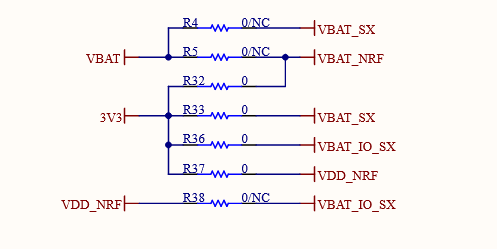
This is used in our RAK10702 Indoor Air Quality device and in our RAK2560 SensorHub.
Thanks for the reply.
The reason behind using the RAK4631 and not RAK 4630 module is because I would like to use the base board only to flash and configure the Core module. After that I would remove the 4631 and place it on my custom board where I am also going to place the 40 pin connector.
You cannot supply through the 3.3V of the SWD header.
Thanks, for clarifying this.
So if I understood correctly, there shouldn’t be a need to solder or desolder any resistor from from RAK4631 as long as I supply the two voltages (VBAT_NRF < 5.5V and a clean 3.3V) through the 40 pin connector, right?
If you want to use the RAK4631 Core module without the base board, you still have to supply through the 40 pin connector on the bottom.
Can you confirm that Pins 5 and 6 are the ones used to supply 3.3V to the SX1262?
Now regarding current consumption, which one consumes the lowest? RAK4630 or RAK4631?
Thanks
(1) Correct, if you supply VBAT and 3V3 through the connector, the Core module will work.
(2) The pinout of the 40 pin connector is in the datasheet. For a proper power supply use the green marked pins. (VBUS only if you add a USB connector):
(2)
Perfect, thanks a lot Bernd.
Is there any reason we couldn’t supply 3V3 and VBAT from the same 3.3v source? I know the RAK19007 has a min battery voltage of 3.3v so shouldn’t this be okay to supply that voltage to both? Is there a downside to doing it this way?
We don’t need to worry about handling power when USB is connected, just for operation from a battery source (that is regulated to 3.3v).
Welcome to the forum @KeithMon
The batteries used on the RAK19007 are 3.7 to 4.2V. If the battery voltage goes lower the regulator for the 3.3V is starting to draw a higher current, because its input voltage is below the specs.
For the RAK4631 itself, the 3.3V is for the SX1262 LoRa transceiver, VBat is feeding the DCDC converter of the nRF52 which generates its own 3.3V supply. The nRF52 datasheet says the nominal voltage should be 3.7V, but the range can be from 2.5 to 5.5V.
With only 3.3V on VBat I would expect a higher consumption of the RAK4631 due to its setup.
Thanks @beegee!
I noticed the SGM6036 regulator on the RAK19007 has a passthrough mode (100% duty cycle). It appears that when the battery voltage is near or less than the output voltage setting (3.3v), but above the UVLO threshold, the buck regulator will pass voltage straight through. This seems like it would use less power.
Do you happen to know how much extra power consumption we’re talking about when using 3.3v input to the nrf52 internal regulator?
I’m already pretty happy with the current draw when supplying 3.3v to the battery connector on the RAK19007. It’s about 35mW when using Meshtastic firmware (average consumption over a couple hours to account for periodic TX). I’m using an external solar battery charger module and it’s actually feeding between 3.35v and 3.4v into the battery connector.
If the inefficiencies are already built into the overall power consumption I’m seeing (35mW) then maybe we’re talking about pretty small amounts of additional power consumption when supplying 3.3v to both.
Sorry, I did not extensive tests about the single power supply solution, I do not have RAK4630 here, only RAK4631. HW engineering said ~5uA higher consumption when using the single supply voltage.
Thanks for checking. This helps me make an informed decision on the power circuit design.
For my application, 5uA isn’t enough to warrant two power rails.