Hi RAK team
I’m using a RAK6421 WisBlock Pi HAT with two SX1262 modules (one in each IO slot - yes I knoooow it’s a long shot) and I’m trying to run both radios concurrently on a Raspberry Pi 4. Loving the board so far - just hit one hardware detail I need your help with.
The issue I’m working around:
- Slot-1’s SX1262 BUSY and slot-2’s SX1262 NRESET both land on the same Pi pin, BCM GPIO24 (net
IO24). - So whenever slot-1 is active (BUSY low), it holds slot-2 in reset — the two radios can’t run at the same time as-shipped.
- From the schematic, the fix looks straightforward: open solder-bridge
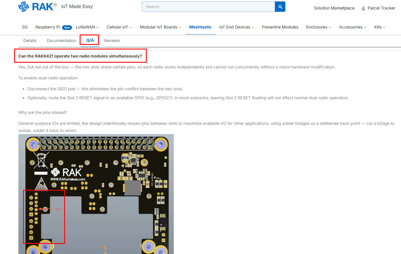
SB21(slot-2 J2 pin 32,IO4 → IO24) and re-home slot-2’s NRESET, leaving slot-1 untouched.
Where I’m stuck:
- The board has no
SBxxsilkscreen labels, so I can’t tell which physical jumper is SB21. - The datasheet page shows “No downloads,” so I don’t have a placement file to go by.
- I’ve confirmed the net mapping from the schematic (SB21 = slot-2 IO4→IO24, with SB22 = IO4→AIN1 right next to it) — I just can’t pin it to a physical pad on my board.
What would help enormously:
- The PCB assembly drawing / silkscreen overlay (top + bottom), or
- A component-placement / fab drawing, or
- even a high-res annotated photo showing where the
SB17 / SB21 / SB22jumpers sit relative to the J2 connector, J8 breakout (AIN1/IO4/IO5/VBAT), and J9 header.
Basically: which physical jumper is SB21, and where is it on the board?
Bonus question if it’s easy: is SB22 (IO4→AIN1) open by default, and is SB17 (slot-1 BUSY→IO24) the matching bridge on the slot-1 side? Just confirming my understanding of the IO24 collision.
Thanks so much for any pointers - happy to share what I find back with the community once I’ve got it working!