Issue: My Wisnode V1.2 is not responding to any AT commands via arduino interface. There is no problem communicating via RAK Serial Tool.
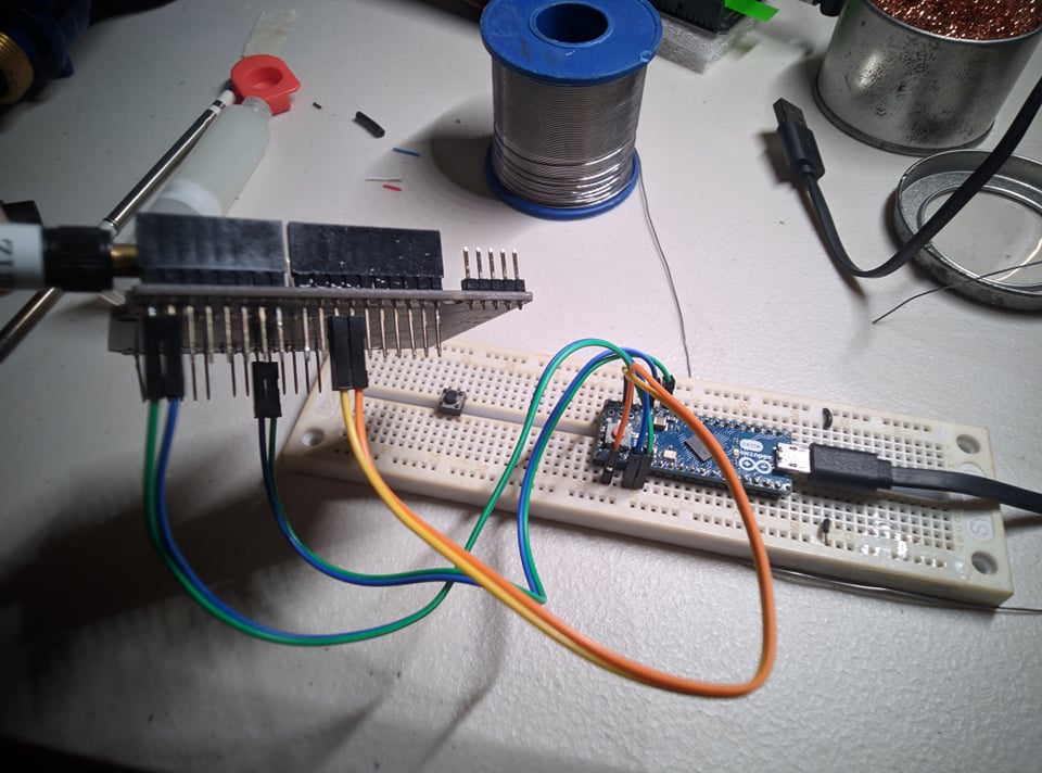
Setup:
I have followed the github guide for interfacing (GitHub - RAKWireless/WisNode-Arduino-Library: This repo is used for Arduino board + WisNode-LoRa RAK811 board.). However, I am using an Arduino Micro instead of an Arduino Uno. I tried using the JoinNetworkOTAA example as well as just using a plain sketch to send/receive AT commands via serial monitor. The extra 2 jumper wires are for the DebugSerial as specified in the sample sketch (Pins 10/11)
I’ve also configured the UART1 to be at 9600 baud via RAK Serial port.
Key steps I took:
Upgraded the firmware using the one provided in the github repo (3.0.0.13t1)
Also, can you try some tests to isolate which cause? Have you tried to connect your RAK811 WisDuino board to the network server just by doing AT commands first? Can you have check the SW serial pins of the Arduino if there’s really an output by using USB-UART converter? Are the uart pins on 2 boards TX<->RX and RX<->TX? Do you have multimeter to check if the pins of 2 boards are really connected? Sometimes, there are breadboard and jumper wires that are reliable.
If the RAK811 is working fine and the resistors are removed with proper jumper settings, it is mostly like related to the jumper wires or the Arduino. It is good if you can get a USB-UART converter to check. If you have access to oscilloscope or logic analyzer, you can use that too to check.
Btw, I think you can use the USB-UART chip of RAK811 WisDuino.
Anyway, let’s avoid other complications now. Just get a USB-UART converter and check
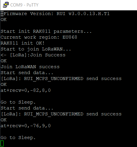
I got the USB-UART converter and monitored the serial communication from the arduino. I have verified that the arduino actually sends the correct serial commands from my specified serial pins. However, the wisnode does not respond at all so I have a suspicion that there is a disconnect somewhere between the arduino and wisnode.
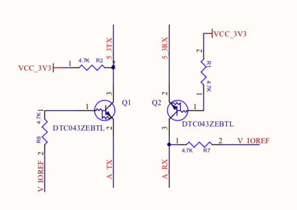
What I did to check was to connect the arduino serial pins directly to the TX/RX pin of the RAK811 instead of using pin 1 & 2 and the jumper. This way, I was able to communicate with the Wisnode but I think this is not recommended because I am pushing 5V to a 3.3V chip so I immediately stopped doing it after confirming the issue. Why is this so? Is there a jumper that I forgot to remove/attach?
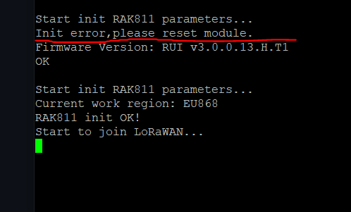
Here’s the communication monitored via USB-UART. The first lines are from using pins 1&2 + jumper on TXD / RXD. 2nd one is directly connecting to TX/RX of RAK811.
On D10 and D11, you should be able to see exchanges of AT commands.
If I understand correctly, the Arduino and RAK811 works if they are tested individually? Though I don’t clearly see how you tested it on your last message.
If you think the problem is the connection between RAK811 and Arduino, could it be the voltage level shifter section? At this point, it is hard to see without oscilloscope or logic analyzer.
I tested the Arduino serial pins by checking the output via the USB-UART connector (CP2102), at+version etc. commands were being sent. RAK811 was tested by using the onboard USB-UART through RAK Serial Tool and it was working.
The setup where the arduino + RAK811 is working is when the Serial pins are connected directly to the UART1_TX / RX pins and not going through the level shifter section (as you pointed out).
Regarding the IOREF pin, I did not connect any supply to it.
So the connection where the Arduino + RAK811 works is:
Arduino → RAK811
TX → RXD
RX → TXD
5V → 5V (Pin 5)
GND → GND (Pin 6)
For the debugserial, I used D14 & D16 and connected it to the CP2102 USB->UART. The screenshot I took was the serial monitor of the CP2102.
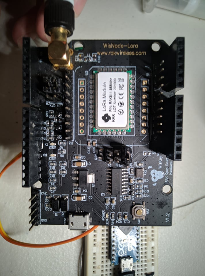
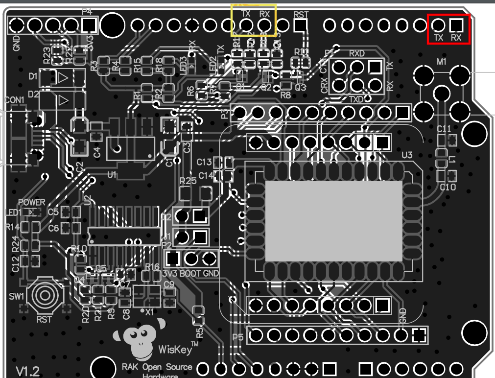
Just for confirmation, I am connecting the TX/RX pins from the arduino to the pins inside the red box. Should I connect it to the TX/RX pins on the yellow box?
There is a conflict of information between the guide in RAK docs and the guide in github.
In the RAK docs, the ATSerial used was pins 0 and 1 (Hardware Serial). While in the github guide, the ATSerial used is pins 10 and 11 (SoftwareSerial). This causes confusion since the github guide does not have a wiring guide for those that are not stacking the arduino on top of the wisnode.
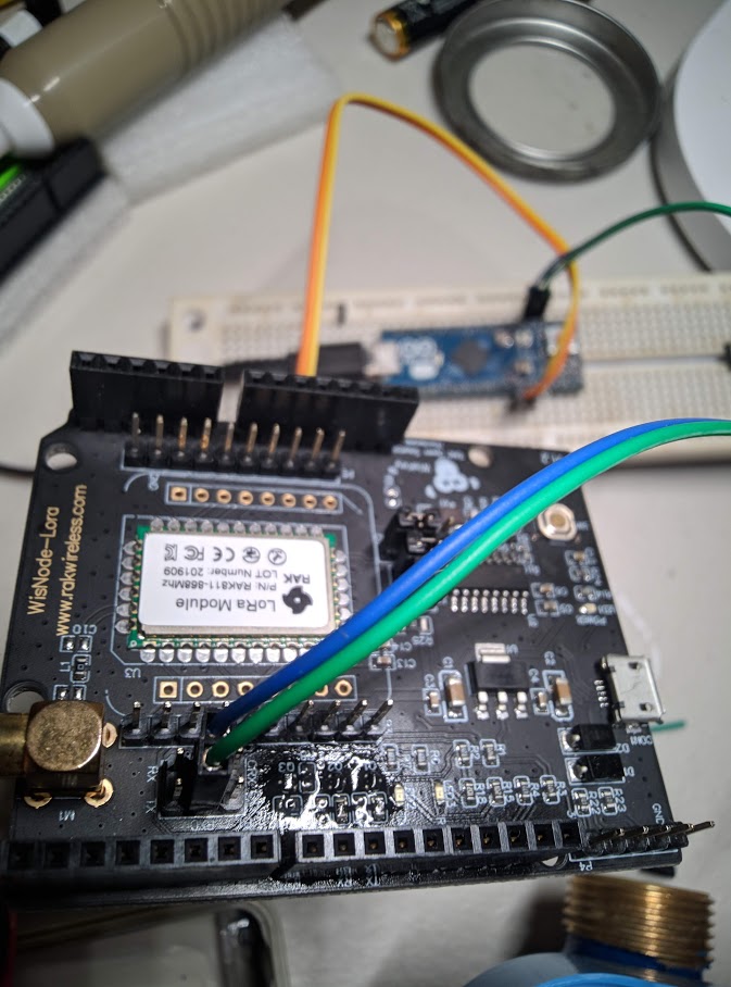
So the correct wiring method for those that will follow the github guide and not use the UNO is:
Arduino → RAK811
TX/RX (pin 10 &11) → TX/RX of the yellow box (yes, tx connects to tx indicated in the silkscreen)
5V / GND → Pin 5 / Pin 6
For the debug,
TX/RX of Arduino (pin 0 & 1) → RX/TX of the USB to UART adapter.