Hi,
I’m trying to use the at+get_config=device:gpio:X to read a GPIO pin.
I’m assuming that the command will initialize the GPIO as input by default. Cold you please confirm ?
What’s the default for the GPIO pins ? Open-drain/pull-up/pull-down ? I’d think open-drain as multiple readings on the same pin give random 0/1 results.
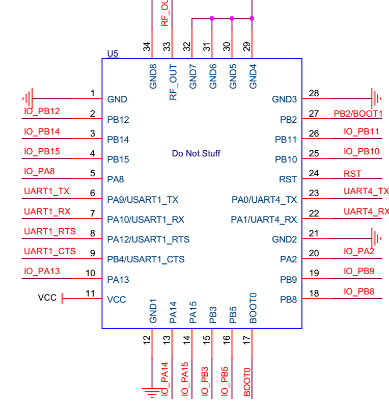
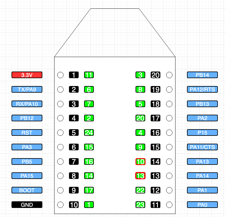
Another issue is that I can’t find a mapping between the parameter of the AT command and the GPIO pin number as described on the breakout board.
The only one that seemed to work was at+get_config=device:gpio:23 that was reading PB14, PIN 11 on the diagram.
Thanks,
I’m assuming that when you say GPIO3 you refer to the value I’d use in the AT command, right ?
As you can see, multiple reads give different values, if the pin was configured with pull-down, I’d expect to be always 0
at+get_config=device:gpio:3
Pin level is:1
OK
at+get_config=device:gpio:3
Pin level is:0
OK
at+get_config=device:gpio:3
Pin level is:1
OK
at+get_config=device:gpio:3
Pin level is:1
OK
at+get_config=device:gpio:3
Pin level is:1
OK
at+get_config=device:gpio:3
Pin level is:1
OK
at+get_config=device:gpio:3
Pin level is:1
OK
at+get_config=device:gpio:3
Pin level is:0
OK
at+get_config=device:gpio:3
Pin level is:1
OK
Also, PB14, on the breakout board positioned in the lower right corner, for me works when using the following: at+set_config=device:gpio:23:0
As for the errors, that’s what I get
at+set_config=device:gpio:13:0
ERROR: RUI_AT_PARAMETER_INVALID 2
at+set_config=device:gpio:10:0
ERROR: RUI_AT_PARAMETER_INVALID 2
while it works fine for the others
at+set_config=device:gpio:9:0
OK
at+set_config=device:gpio:4:0
OK
at+set_config=device:gpio:20:0
OK
at+set_config=device:gpio:5:0
OK
at+set_config=device:gpio:8:0
OK
at+set_config=device:gpio:3:0
OK
at+set_config=device:gpio:2:0
OK
at+set_config=device:gpio:15:0
OK
at+set_config=device:gpio:16:0
OK
at+set_config=device:gpio:14:0
OK
Thanks Leopold.
I’d suggest you guys update the documentation on the breakout board and the default GPIO status of PIN_OPEN_DRAIN.
I’d also suggest to add the capability of configuring the GPIO inputs with an internal pull-up.