I am trying to do a simple serial TTL connection with the RAK2270 and the RAKDAP1 on the old Arduino IDE. I have first made sure that it works using my old method of an Arduino supplying 3.3V (and GND) and a TTL to serial cable to GND, RX and TX. That works I can program and get serial output.
Then I have tried the RAKDAP1 connecting 3.3V, GND, u_RX, u_TX. The port shows up on the Arduino. The RAKDAP1 folder opens, device manager says it is working properly, but no serial connection. I have tried switching RX and TX just to make sure.
Does something have to be installed? Do I have to use SWD or JTAG? Any suggestions?
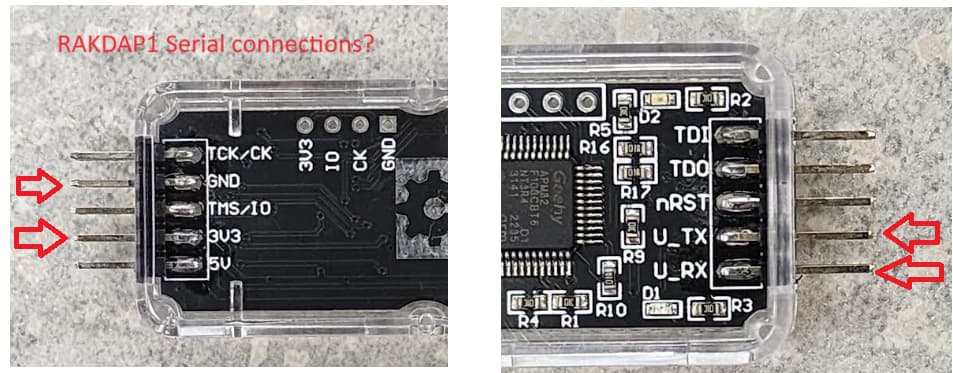
By the way if I was to use SWD or JTAG the pin names are not what I am used to. Any suggestions for this second issue. (The first issue is more important.)
But I still need to figure out the USB serial. I think perhaps a regular USB TTL cable will work better for my use case with windows than the RAKDAP1. Does that make sense?
Can SWD be used for serial connection? I was expecting UART using RX and TX? @beegee
By the way I use the old Arduino IDE so I need the com serial port, but I also use webSerial which should allow the same serial port to be accessible from webPages.
The RAKDAP1 can be used as USB-Serial and also as external debugger/programmer via SWD pins.
I am not sure what could be the problem. Maybe you can double check the header jumper wires if continuity is ok? Does the LED on the RAKDAP1 lights up if you try to send something?
So definitely some weird stuff happening with the RAKDAP1 and a Serial RAK2270 Connection (3V3, GND, RX, TX) worse on Windows than on Linux. The problem is the Arduino IDE and how the Arduino serial monitor works. Linux is more stable than Windows. When I had connection issues on Linux a simple laptop reboot was all that was needed.
Here are my steps on windows. (hopefully you will not need them)
laptop reboot
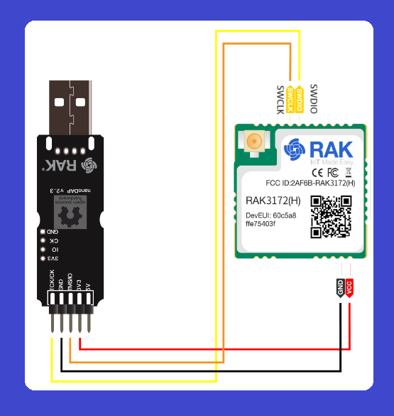
Make sure RAKDAP1 is connected to 3V3 and GND is connected
Make sure to switch RX and TX.
RAk2270 TX goes to RAKDAP1 RX and
RAK2270 RX goes to RAKDAP1 TX
Open Arduino IDE
Connect RAKDAP1 to serial port
on Arduino IDE find serial port and open a fresh serial monitor
Unlike RAKDAP1 instructions, use 115200 baud
other settings don’t matter Arduino default “NewLine” is fine.
run AT+BOOT then AT+RUN to reset the board and see any print-out
Much easier on Windows to use “putty.exe”
Use the DOS mode command to find which port and then switch putty.exe to serial–>which COM → which speed -->115200 → AT+BOOT -->AT+RUN
@carlrowan I have used the Particle DAP Debugger before and really liked it. Would the programming process be similar with the RAKDAP1 when properly connected for SWD communication?
On the Arduino IDE save your code, then in Sketch–>export-compiled-binary which produces a .hex file in that saved folder. Then drag that .hex file onto the RAKDAP1 folder.
Something nice about this approach is the ability to save working binaries and not having to compile them each time.
RAKDAP1 works with pyOCD. This means you have to do things in terminal (not really good news if you want GUI based clicking or drag-and-drop).
However, you can use WisToolBox on RAK2270. It will be able to detect RAK3172-SiP then you can do reconfiguration, saving different templates and also save your different firmware (but should be in .bin format not .hex since you only need to compiled RUI3 based firmware application file and not the bootloader of RUI3).
Hmmm. I know nothing about the wiseToolBox, is that something I should look into? Probably not, since my goal is ultra simplification and the Arduino platform is about as easy as it gets. This link WisToolBox - Tool for LoRaWAN Configuration, Firmware Update and AT Commands - RAKwireless - IoT Made Easy does make it look interesting, especially the Android BLE connectivity, but I don’t remember anything about the RAK2270’s having BLE. Any clarification
For RAK2270 which is based on RAK3172-SiP, Wistoolbox desktop via UART connection is the only option since it has no BLE. But for other Wisduo modules, like RAK4630 and RAK11720, these are hybrid modules (combination of LoRa and Bluetooth) so BLE is supported (RAK11720 is only desktop for now but soon mobile app as well).
Since you are looking for solutions where you can store various firmware builds for your RAK2270, my suggestion is wistoolbox. But of course you need access on UART pins.
@carl. It is also not obvious on WiseTolBox how to make a simple sketch that just communicates with the Serial monitor. Perhaps when I connect a device this part will become more clear.
Not finding a youtube about it but have found
which leads to this
So I am good now. I will see what I can do tomorrow.
It is purely UART @jerteach . Will you be able to test first the connection via separate serial terminal and try some AT commands first? Also you need to ensure that the COM port used by RAK2270 is not open else, it will not be detected by teh WisToolBox.
Hi @carlrowan I just read some more and I think I am more interested in ways to code the RAK2270. I just read that I would need to make a .bin file from the Arduino IDE and then upload it. I think I will go back to the SWD connections and see what I can do.
Ideally I still want to upload from the Arduino IDE a .hex file to the DAP folder. Which is something I have done with other microcontrollers using a DAP debugger. I will do some testing tomorrow. I still haven’t ordered the RAK clip, yet so I may just solder wires to the pads. My DIY clip is not good enough for this kind of testing.