Reading external battery voltage and USB serial voltage separately on RAK-5005-O (V1.0)

Greetings !

I am running the “RAK4630 Battery Level Detect” github repo example using the RAK5005-O baseboard and RAK4630 on the CPU slot.

I need to find some method to differentiate between the external battery voltage and voltage being supplied by the serial USB connection. In the example, the voltage value is being fetched from the WB_A0 analog channel of RAK4630.

From the schematics of baseboard RAK5005-O (CPU Slot) , there are separate pins for checking the external battery voltage and USB voltage as indicated below :

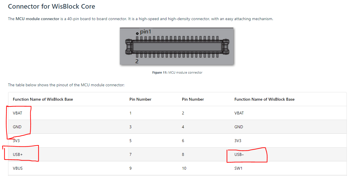
I have confirmed it by using a multi-meter on these pins and it shows me correct voltage for external battery (when connected across Pins 1-3) and also for USB serial voltage (when connected across Pins 7-8).

However, in the following pin mapping between RAK4630/1 and nRF52840, it doesn’t seem possible to single out these CPU slot pins.

 * @note RAK4631 GPIO mapping to nRF52840 GPIO ports
   RAK4631    <->  nRF52840
   WB_IO1     <->  P0.17 (GPIO 17)
   WB_IO2     <->  P1.02 (GPIO 34)
   WB_IO3     <->  P0.21 (GPIO 21)
   WB_IO4     <->  P0.04 (GPIO 4)
   WB_IO5     <->  P0.09 (GPIO 9)
   WB_IO6     <->  P0.10 (GPIO 10)
   WB_SW1     <->  P0.01 (GPIO 1)
   WB_A0      <->  P0.04/AIN2 (AnalogIn A2)
   WB_A1      <->  P0.31/AIN7 (AnalogIn A7)
 */

Any leads would be appreciated. Thanks.

Welcome to RAK forum @rommel :slight_smile:

The output of the on-board charger in the base board is directly connected to the battery. There is no way you can separate the output of the charger to the battery without doing any hardware modification.

Can you share your goal why you want to do this? There might be other possible work around.

My goal is to identify , at any instant, if the board is being powered through USB serial or through the external battery.

Hi Rommel,

Sadly there is no way you can have that unless you do a sensing connection from VBUS pin/trace.

You can check the schematic of RAK5005-O base board here RAK5005-O WisBlock Base Board Datasheet | RAKwireless Documentation Center

Since A0 is already connected to the battery, there is no more Analog input available in the header of the base board. You can probably create a voltage divider on the VBUS pin/trace then put it to IO1 or IO2. Then check the status digitally. But again you need to do few soldering tweak to achieve this.

Right, thanks for the assistance.

This topic was automatically closed 2 days after the last reply. New replies are no longer allowed.