
Thinking this is not possible due to the pinmapper screenshot. Could this be confirmed please? Is there any way to get these two together on a board?


Excellent, I’ll have a crack at it. I don’t actually need the buttons that come with the e-ink if that could provide an easier solution?
Hi Andy,
The buttons are on different GPIO’s and would not help to make it easier.
Only just getting back to this project. So once the soldering and bridges are completed, what are the pin allocations for the relay called?
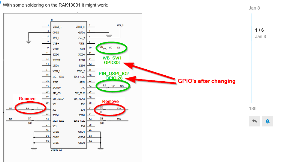
Oh wow, you can clearly see what you’re dealing with here @beegee, apologies for my complete lack of observation/knowledge!!
1 Like
Have made the necessary changes to the code and it seems to be working. The new issue I have is I need an interrupt counter. Is WB_SW1 available for this? I’m not using the opto-couple isolated input function of the relay. If not this, then is there another pin available? I’m using the RAK19001 WisBlock Dual IO Base Board. I thought IO8 might be available (it’s got a header available), but my understanding is it’s not able to be used with the 4630.
IO8 should work on the RAK4631, it is GPIO 0.02, but it is not defined in the variant.h (most other Core modules do not support IO8).
This topic was automatically closed 10 days after the last reply. New replies are no longer allowed.