
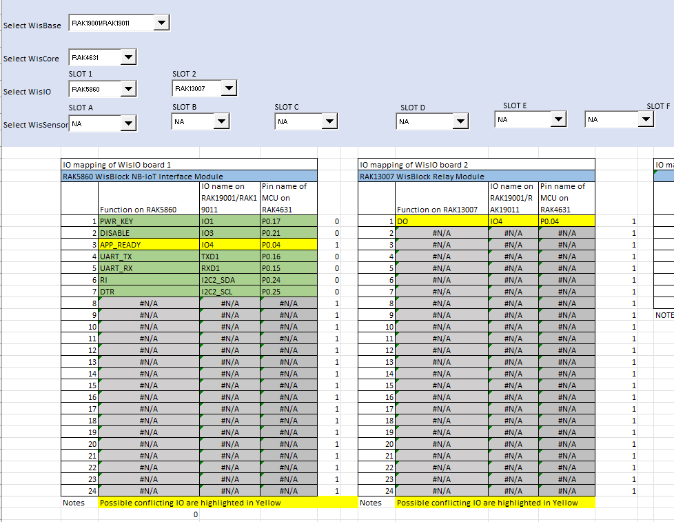
Hi, I’m looking at attempting to build a remote pump switch. As I’d like to use the RAK13007 (Relay Module), I think I’d have to use the RAK19001 (Dual IO Base Board) with the RAK5860 also required. The pin mapping indicates there is a conflict with IO4. I’ve added a screenshot.
The alternative would be to purchase the RAK416005, add an external relay and utilize a pin to enable it? I assume this would be possible?
Thanks for any assistance. Andrew.
With the RAK5860 it will be difficult to get enough GPIO’s.
My solution, but works only with RAK4631:
I am running two relays on a RAK19001 by changing the controlling GPIO on the RAK13007.
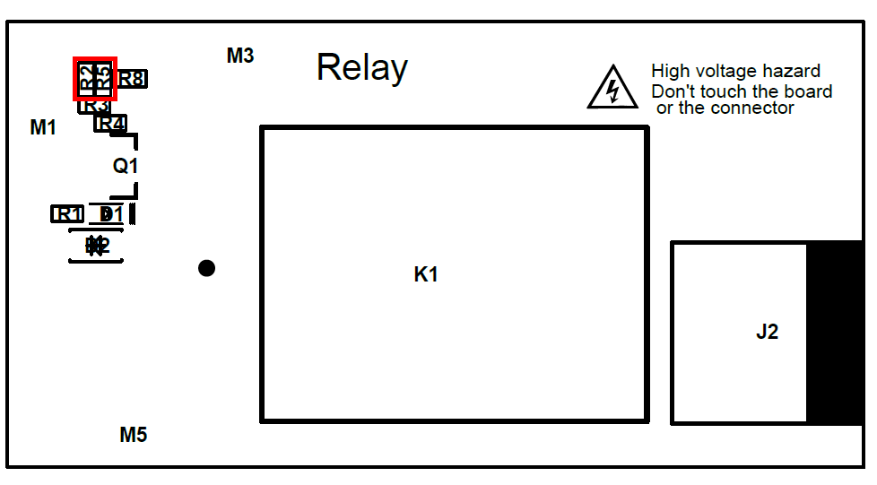
Remove R5 and put a solder bridge on R2. Then the relay is controlled by WB_IO7.
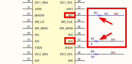
The RAK11200 and RAK11310 do not have IO7, so the only option is to use the I2C2_SCL (which is not used on any module).
thanks @beegee, I’ll have a think about whether that’s worth doing. The alternative would be the Blues.ONE - LTE-M NB-IoT GSM LoRaWAN Device based on nRF52840, SX1262 and Blues.IO Notecard. Arduino compatible
SKU: 415007
I assume with this setup I could assign an IO pin high/low to trigger an external relay?
I would also be looking to send a periodic uplink with the I/O status to indicate state. Does all this seem doable?
Yes, the RAK13102 NoteCarrier module is using only I2C_1 and IO5.
That leaves you other IO’s free for a relay control.
The Blues.ONE comes on a RAK19007 Base Board. But you could use
RAK19001 Base Board
RAK4631 Core Module
RAK13007 Relay Module
RAK13102 Blues NoteCarrier Module
to get the same + relay on the dual IO Base Board.
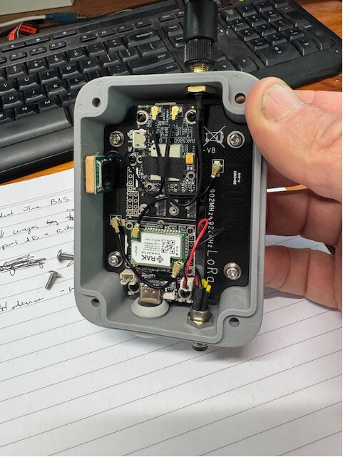
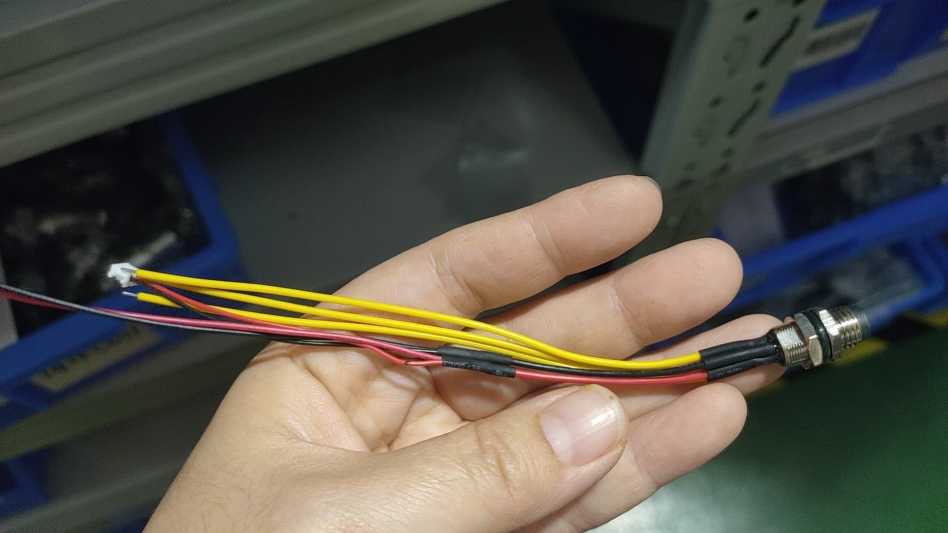
Just received a couple of these devices to play around with, and it looks like a really neat package. One question/problem is that the 5 pin connector, three of the wires in the box have been cut so short it’s going to be really difficult to extend for the pump control to be added. Any reason they’re cut so short? It defeats the purpose of 5 pins.
Another problem is that when ordered without the battery, you have to break the gps glued position to take the board out, it would be better on the other side of the enclosure so the board can be removed easily.
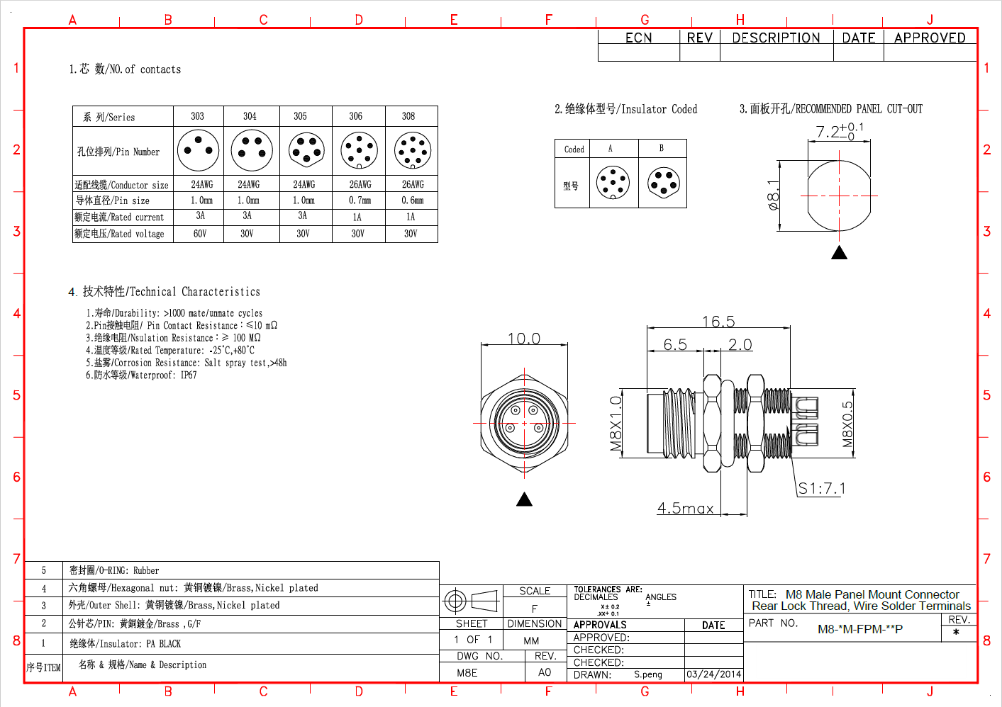
Looking to replace the connector, does anyone have the product code/link to where I can find a replacement? Called " * With 5-pin M8 connector for signal IO and external 5V supply or solar panel" There’s nothing listed on the RAK website.
Thank you for the feedback @Andy
Regarding the short cut cables, I complained in the past to our production, but it didn’t change (yet). I will talk with them again.
The GPS antenna is on this specific side for a reason. When using the mounting plate with the integrated antennas, there should be nothing above the antennas.
The BLE antenna is very short, so the GPS antenna was placed on that side. The LoRa antenna is much longer and left not enough space for the GPS antenna.
For the M8 connector, I will ask our production for manufacturer number. I hope it is not something made special for us.
Thanks for the explanation @beegee, I’ll just have to remove/replace the gps upon receiving the devices to insert battery. All good.
I’ll be keen to hear about the M8 connector. It’ll make it a lot easier, as I need to solder to gpio pins.
Not much luck with the M8 connector part number yet.
We buy it not as a single connector, but as a pre-configured cable assembly from a Chinese supplier.
Still trying.
Cool. How do I order something like that? AliExpress?
As far as I know, the M8 connectors are a “standard”. You might be able to order it locally.
Important is
- 5 pin
- coding B
I read this post and made the 13007 changes. When i add WB_IO7 to my code, it doesnt exist in the 4631 WB_IO7 variant.
IO7 is not in the definitions as WB_IO7.
I guess because other boards do not support it, only the RAK4631. And when the RAK4631 was made (in 2020), the pin was intended to be used for a flash memory chip.
You can define it in the code with
#define WB_IO7 28