
hello everyone, while waiting to receive my RAK3172 and my new PCBs to apply all the changes that you have provided to me, I am getting ahead of my V3 prototype, who can tell me if my accelerometer wiring is correct ?
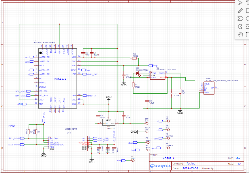
Looks like your connections to the LIS2DH are same as in the data sheet.
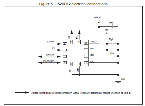
We do not have a module with the LIS2DH, only with the LIS3DH, so cannot say whether it is working or not.
hello, yes indeed, for the moment I am testing with the LIS2 because I have a pre-mount available, do you think it is possible to couple the RAK3172 timer to the LIS2 or LIS3 to wake up the module in the event of movement?
I am using the LIS3DH to wakeup the RAK3172 in a location tracker app RUI3-RAK12500-RAK1904-GNSS (see RAK1904_acc.cpp)
I guess it is similar for the LIS2DH, but you have find out what registers you have to setup and connect one of the INT pins to a GPIO of the RAK3172.
yes I saw the example on github and also your message on the forum for the PINs, so I think that this would be possible to achieve, I will see and modify the example script to adapt it to my PCB, the The difficulty will be to stop the GPS when the cycle starts, thank you.