I want to use the WisBlock to read out an SDI-12 sensor. Does anyone know if it is possible using the RS485 interface (Transmit data efficiently with the LoRa®-powered RAK5802 module – RAKwireless Store)? I saw somewhere on the internet that someone used only the one connection from the RS485 differential pair, and connected that to the SDI-12 sensor. The other connection from the differential pair is then either left floating, grounded, or pulled to Vcc.
Or does RAK maybe plan to make an SDI-12 interface card for the WisBlock?
Hello JP,
I doubt that it will work with the RAK5802 module, but could be worth a try.
We are collecting customer feedback about interfacs/sensors that they would like to see supported by WisBlock and I will add your request to our list. But I cannot promise you anything.
I tried to speak SDI-12 using the RS485 connector board (RAK5802) today. So far I’m not successful. I’m not sure if I should use A or B, and if it’s fine to pull the other terminal to 3.3V or to GND. And I can’t find the Arduino forum post that described the setup.
Next step would be to try Arduino-SDI-12 but I’m not sure if the WisBlock has a free GPIO I can use for this. And then I’m also not sure if the library needs interrupts or not.
I’ll update here if I find anything. If you have any ideas, please let me know.
Following your need of an SDI interface module I put it on the list of new WisBlock modules for this year. But I cannot promise any availability date. We are planning at least 3 events this year where we will present new WisBlock modules.
At this point I need to find a way to test the viability of using the WisBlock to read out SDI-12 soil moisture probes. It needs to happen asap, as it influences business decisions.
We can’t wait for RAK to release a new comms module every time we want to do something new/custom. In this case the best is to find a way to directly interface with the WisBlock without a connectivity module. I’ll search for the docs and see if there is a GPIO which can be used.
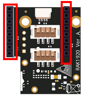
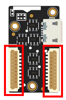
the RAK1920, which has several GPIO’s, SPI and I2C exposed on the Click! connector.
or the 5804 which has all available GPIO’s, I2C, Serial and SPI exposed on a small connector. It comes with a matching connector and cable to connect external devices.
Yes, that is a good idea. What do you think about the J10 and J11 headers on the base board? I see J11 has a free GPIO on pin 2. That might work. I’m still looking through the documentation of the WisBlock to figure out exactly how to use these pin from Arduino.
We know about the confusing different naming of GPIO’s on the RAK5005-O and the RAK4631.
In the next release of the Arduino BSP we will have all RAK5005-O GPIO’s predefined and linked to the correct GPIO numbers of the RAK4631.
I was able to get SDI-12 working on the Wisblock using SoftwareSerial. The ArduinoSDI12 library didn’t work, even after I hacked it to use the micros() timer for timing.
SoftwareSerial does not support any other serial mode than SERIAL_8N1. But SDI-12 uses SERIAL_7E1. I therefore manually add a parity bit to every byte before I transmit, and I ignore the parity bit on rx.
Thank you for the welcome @beegee
I haven’t tested it on the RAL13010 hardware yet, but it should integrate quite cleanly because the library was designed around making small hardware adapters.
It is architecturally very different from other libraries like Arduino-SDI-12 libsdi12 does not implement any GPIO or UART logic itself, rather it exposes a few callbacks.
send() transmit bytes
recv() recieve bytes
set_direction() which switches the bus between TX and RX
delay_us() timing
Because of the callback design HAL is 20-50 LOC
RAK13010 uses three GPIO(TX/RX), direction control.
This maps very well to the library.
The actual SDI-12 protocol is handled inside of the library, i.e command parsing (M, C, D,I), timing rules, CRC commands, sensor addressing, measurement state and behavior.
So the wisblock sketch ends up only implementing the hardware adapter, registering the sensor parameters and providing a callback that returns measurement values.
One reason I wrote it this way is SDI-12 implementations are usually coupled to a specific MCU or UART configuration like Arduino-SDI-12 using software serial, which makes certain use cases hard if outright impossible i.e interrupts .
This version is pure c with zero dependencies, so it will work on anything from a small ATmega328 to a SBC running embedded Linux independent of actual UART implementation, to the best of my knowledge it is the only library to practically implement the entire SDI-12 standard everything else only complies to a subset of the standard.
I am also in the middle of developing a SDI-12 Verifier tool, which uses the lib; So far I have only had the chance to test it via loop-back. GitHub - phillipweinstock/libsdi12-verifier: Open-source SDI-12 v1.4 compliance tester with 21 automated sensor tests, microsecond timing measurement, and text/JSON reporting. · GitHub I need to refactor the libsdi12 build system in order to make shared libraries, so software relying on it is easier to package.