I’ve got a sketch that takes incoming TTL data on the UART and parses it. The listener is on Serial1 and it’s doing exactly what it needs to do. Now I want to take the messages and send them to Hologram via the 5860, using the BG77 Hologram_Tcp example as the basis.
The problem I’ve run into is that both the UART and the modem are designated as Serial1 and I want to have them both listening concurrently. How do I disambiguate the interfaces?
I still do not get it. Maybe I do not understand how the devices the UART and the modem (I think this is the RAK5860) are connected to WisBlock Base and RAK11310 core.
Yes, it is the RAK5860 in IO slot A on a dual IO 19011 base board. The UART is exposed on pins TX01 and RX01 of J18 and I am only using RX01. I tried moving the modem to IO slot B and nothing changed.
I hope I understand now that the UART device and RAK5860 share same UART lines.
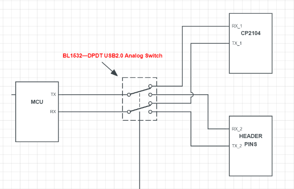
This is tricky. One possible way to make this work is use RX1 to parse the data from your UART device then use TX1 to send command to RAK5860.
However, this is only possible to work if you can isolate both TX side of the UART device and RAK5860. Electrically speaking, if they are connected physically together, I am not sure what will happen since both pins are not in high impedance state (I assume since they are both output).
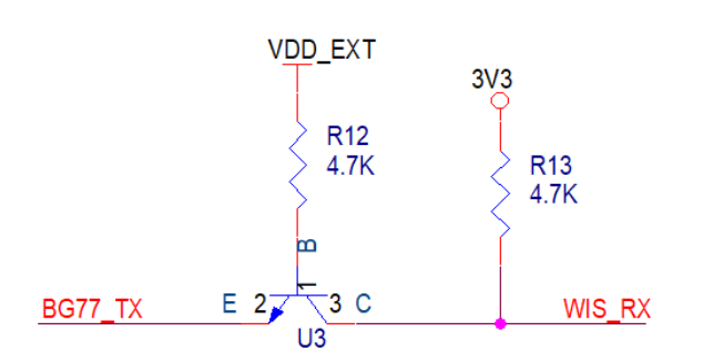
If you really want to push this, since RAK5860 has discreet 1.8V to 3.3V level shifter, you can probably remove all this components so that the RX1 of RAK11310 will now be independent solely on the UART device. You sacrifice getting feedback from RAK5860 on this approach.
These are just ideas I can share. We are hacking a way to make this work and I am not sure if this is a good idea.
I don’t actually need to listen to the RAK5860 except when actively sending data to the Hologram network. So I could power off the modem except at transmit times (once every 5 or 10 minutes) and that way I know that what comes in on RX01 is TTL coming from the external control board.
I’m prepared to sacrifice incoming data during transmit cycles, as all totals are cumulative and parameters are sent repeatedly.
[EDIT] Thinking about this a little more…I’d rather not power down the modem repeatedly, as in some locations it can take a while to get a good signal from the tower. I wonder if I can use ATQ to mute the TX line of the BG77.
Sort of in a similar spot here, need to talk to an external UART device (need to able to transmit AND receive), and also need to communicate with the BG77 (need to be able to transmit AND receive) and wondering what my options are.
What Base Board are you using?
RAK11310 has two UARTS, one is used by the RAK5860 on the IO slot.
Unfortunately the other one is not available on pin headers, it would require a RAK13002 IO module to access them.
To use both RAK13002 and RAK5860, you need to use the RAK19001 Dual IO Base Board.
Hey @beegee , thanks for your reply. We’re using the Link.ONE WisTrio NB-IOT board. I believe it uses the RAK19007 base board. So from what I understand, the BG77 module (RAK4630/4631) uses UART1? We soldered wires to the RAK4631, on pins 6 and 7 to try and access UART2 for our external device.
However, now we have an issue. We cannot talk to the modem any longer (without connecting anything extra), tried Serial1 and Serial2. HOWEVER< when we use the exposed header pins connected to the external device (which I believe uses the same UART as the BG77), we ARE able to talk to the external device. Any ideas what we might do here?
The MicroUSB on the BG77? I haven’t tried that yet, but the modem is alive, the blue light is on with the green light blinking periodically, it just doesn’t seem to be connected/able to talk to the RAK5361.
USB C on the baseboard is working fine, and we connected an external device to the J10 header which was working fine, we could listen and talk to it. Our issue is that the core can’t communicate with the modem anymore.
The headers let us access our external UART device, and you can see the lights are on on the modem, does that indicate it is functioning normally? We haven’t tried plugging into the modem with a microsUSB directly yet, but do you think that will help debug the lack of connection between the core and the modem?
The USB on the RAK5860 is only for Quectel tools, you cannot send AT commands over it or receive data from the BG77 (as far as I know).
Something is bricked on your device, but I cannot say what it is.
If you have another Core module (without wires on the second UART), try if that still can connect to the RAK5860
If you have another RAK5860 module try that one.
@beegee We removed the soldered wires, we reflashed the FW on the core, unfortunately no change. Is there a way to reset or reflash the modem somehow? Also, are the modem lights (blue solid, green flashing roughly every 2 seconds) indicative of anything in terms of whether or not the modem is functional or corrupt etc.?