However, according to the SX1261 Calculator Tool, the symbol time for SF7 and BW125KHz is 1.024ms … so from my understanding, this value is 1.024ms * 1000us/ms = 1024us
… so, probably i’m not correct, but according to this, should not be the rx_time and sleep_time parameters set to:
uint32_t duty_cycle_rx_time = 2 * 1.024 * 1000 / 15.625;
uint32_t duty_cycle_sleep_time = 10 * 1.024 * 1000 / 15.625;
Sorry in case my mistake is obvious. Any help will be appreciated. Thanks.
Hi @beegee thanks for yout reply … I agree that there are many not clear references. Any member can share him/her experience on this issue? I think It is important to clarify it. Thanks.
Hi @beegee, i’ve made some experiments in order to check how to corretly set the duty_cycle_rx_time and duty_cycle_sleep_time parameters for RXDutyClycle functionality, and here are some of the results i obtained. I set the following parameters in RAK4631-Deep-Sleep-P2P example code for Arduino:
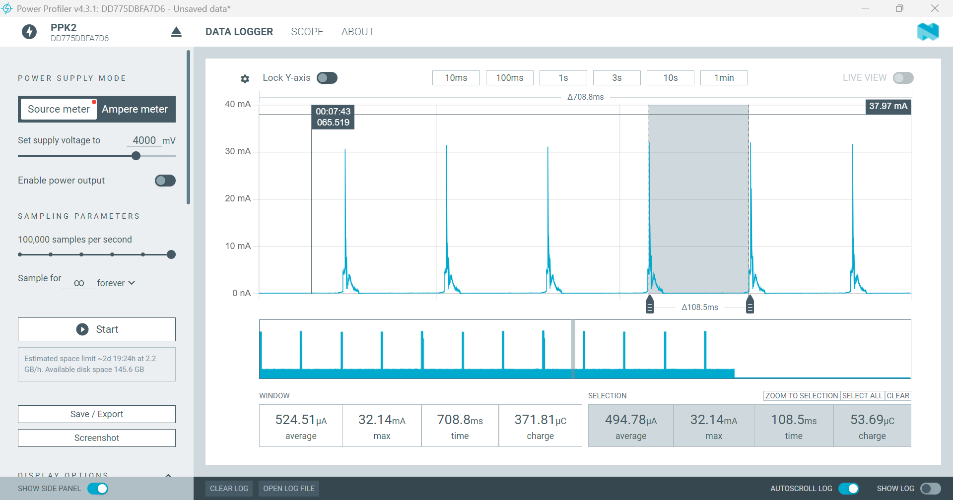
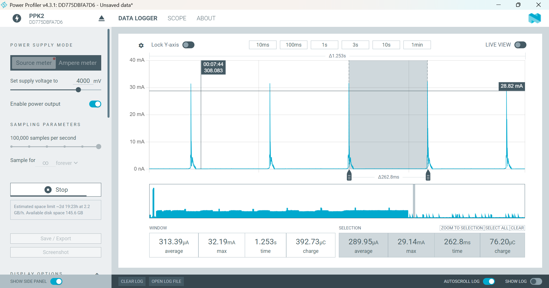
For a preamble lenght of 100 symbols, the number of symbols for rx and sleep were calculated to be 8 and 96, respectively, i.e. 8,192ms and 98,304ms. So, in order to use this values, the duty_cycle_rx_time and duty_cycle_sleep_time parameters were set as following:
From this values, the following results were obtained by using PPK2 from Nordic, where the time interval for rx_time and sleep_time seem to correspond to the calculated values …