
Problem:
I have multiple RAK sensors on my board. Two of them take up slot A and B on my RAK base. The third sensor is on slot C. The one in slot C is a UV sensor. Unfortunately, my RAK board has been unable to detect my sensor in slot C. Is there any way that I can directly tell my board “Hey look in slot C and see what is plugged there?”.
What have I tried so far?
I tried slot D aswell.
I tried an identical version of that UV sensor aswell.
I tried to use the RAK extension cable: RAK19005 and connect the UV sensor to slot C.
I cannot use slot A and B as I screwed my sensors in and I lost the screw-driver that I used to screw them in (Sorry I realise how stupid this is).
Details
RAK core:
RAK nrf4630
RAK base:
RAK19010
It can be found here:
Sensor on slot A
RAK barometric pressure sensor.
RAK1902
Sensor on slot B:
RAK temp and humidity sensor.
RAK1901
Sensor on slot C:
RAK UV sensor.
RAK12019
Code specifications
I modified the RAK UV sensor sample code that can be found here:
modifications
The original code would check if the RAKboard was initialised using !ltr.init(). If the sensor was not recognised by the RAK board then the original code placed the user in a perpetual while loop which said “Couldn’t find LTR sensor!”. Inorder to move past this point I removed the while loop and replaced it with one println statement.
The output that I would get is:
This indicates that no data was picked up.
my code
/*
Mike's modified and commented file.
*/
#include <Wire.h>
#include "UVlight_LTR390.h"
// this creates an object of the class UVlight_LTR390 called ltr
UVlight_LTR390 ltr = UVlight_LTR390();
/*
For device under tinted window with coated-ink of flat transmission rate at 400-600nm wavelength,
window factor is to compensate light loss due to the lower transmission rate from the coated-ink.
a. WFAC = 1 for NO window / clear window glass.
b. WFAC >1 device under tinted window glass. Calibrate under white LED.
*/
void setup()
{
pinMode(LED_BLUE, OUTPUT);
digitalWrite(LED_BLUE, HIGH);
// Initialize Serial for debug output
// Tells you how many milliseconds you took before you started the serial.begin
time_t timeout = millis();
Serial.begin(115200);
// Usually the sensor starts collecting data before you turn on the serial monitor.
// This means that you miss the initial bits of data.
// whilt(!serial) waits until you open the serial monitor so you do not miss those intial bits
// normally all you write is while (! serial);
// we commented this part out as we feared that this was stopping serial communication forever
while (!Serial)
{
// this keeps the loop running until something happens
if ((millis() - timeout) < 5000)
{
delay(100);
}
else
{
//takes it out of the while loop
Serial.println("The board has broken");
break;
}
}
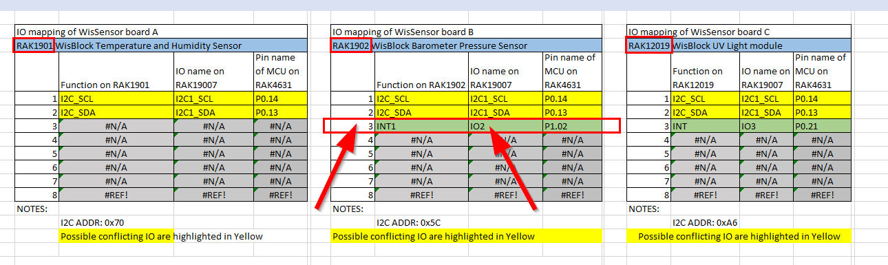
//Sensor power switch
// The module uses WB-102 to power up, since this conflicts with INT1 use slot C and D (bottom slots)
pinMode(WB_IO2, OUTPUT);
digitalWrite(WB_IO2, HIGH);
delay(300);
Wire.begin();
if (!ltr.init())
{
Serial.println("Couldn't find LTR sensor!");
}
//if set LTR390_MODE_ALS,get ambient light data, if set LTR390_MODE_UVS,get ultraviolet light data.
ltr.setMode(LTR390_MODE_ALS); //LTR390_MODE_UVS
if (ltr.getMode() == LTR390_MODE_ALS)
{
Serial.println("In ALS mode");
}
else
{
Serial.println("In UVS mode");
}
// I cannot find any info on what gain is
// this sets the gain to GAIN_3 however, we have to test that the actual gain is actually GAIN_3
ltr.setGain(LTR390_GAIN_3);
Serial.print("Gain : ");
// this switch function compares our current gain to LTR390_GAINS from 1 to 18
// there seem to be 5 different gains that our sensor can have
switch (ltr.getGain())
{
case LTR390_GAIN_1:
Serial.println(1);
break;
case LTR390_GAIN_3:
Serial.println(3);
break;
case LTR390_GAIN_6:
Serial.println(6);
break;
case LTR390_GAIN_9:
Serial.println(9);
break;
case LTR390_GAIN_18:
Serial.println(18);
break;
default:
Serial.println("Failed to set gain");
break;
}
ltr.setResolution(LTR390_RESOLUTION_16BIT);
Serial.print("Integration Time (ms): ");
switch (ltr.getResolution())
{
case LTR390_RESOLUTION_13BIT:
Serial.println(13);
break;
case LTR390_RESOLUTION_16BIT:
Serial.println(16);
break;
case LTR390_RESOLUTION_17BIT:
Serial.println(17);
break;
case LTR390_RESOLUTION_18BIT:
Serial.println(18);
break;
case LTR390_RESOLUTION_19BIT:
Serial.println(19);
break;
case LTR390_RESOLUTION_20BIT:
Serial.println(20);
break;
default:
Serial.println("Failed to set Integration Time");
break;
}
ltr.setThresholds(100, 1000); //Set the interrupt output threshold range for lower and upper.
if (ltr.getMode() == LTR390_MODE_ALS)
{
ltr.configInterrupt(true, LTR390_MODE_ALS); //Configure the interrupt based on the thresholds in setThresholds()
}
else
{
ltr.configInterrupt(true, LTR390_MODE_UVS);
}
}
void loop()
{
if (ltr.newDataAvailable())
{
if (ltr.getMode() == LTR390_MODE_ALS)
{
Serial.printf("Lux Data:%0.2f-----Als Data:%d\r\n", ltr.getLUX(), ltr.readALS()); //calculate the lux
}
else
{
Serial.printf("Uvi Data:%0.2f-----Uvs Data:%d\r\n", ltr.getUVI(), ltr.readUVS());
}
}
else {
Serial.printf("No new data here");
}
delay(500);
}
Apologies
I apologise for not being able to post my code in a readable manner. In stack exchange we can press Ctrl+K and paste our code in a readable and copyable manner. Could someone also tell me how to post code in a legible manner on the RAK forums.
Thankyou so much for your time.


 ). Understanding the reason for a design often helps create a better overall understanding - even if that understanding is just “there was no budget/time to do this better”. Would be great to get some insights if you’re able to share that!