
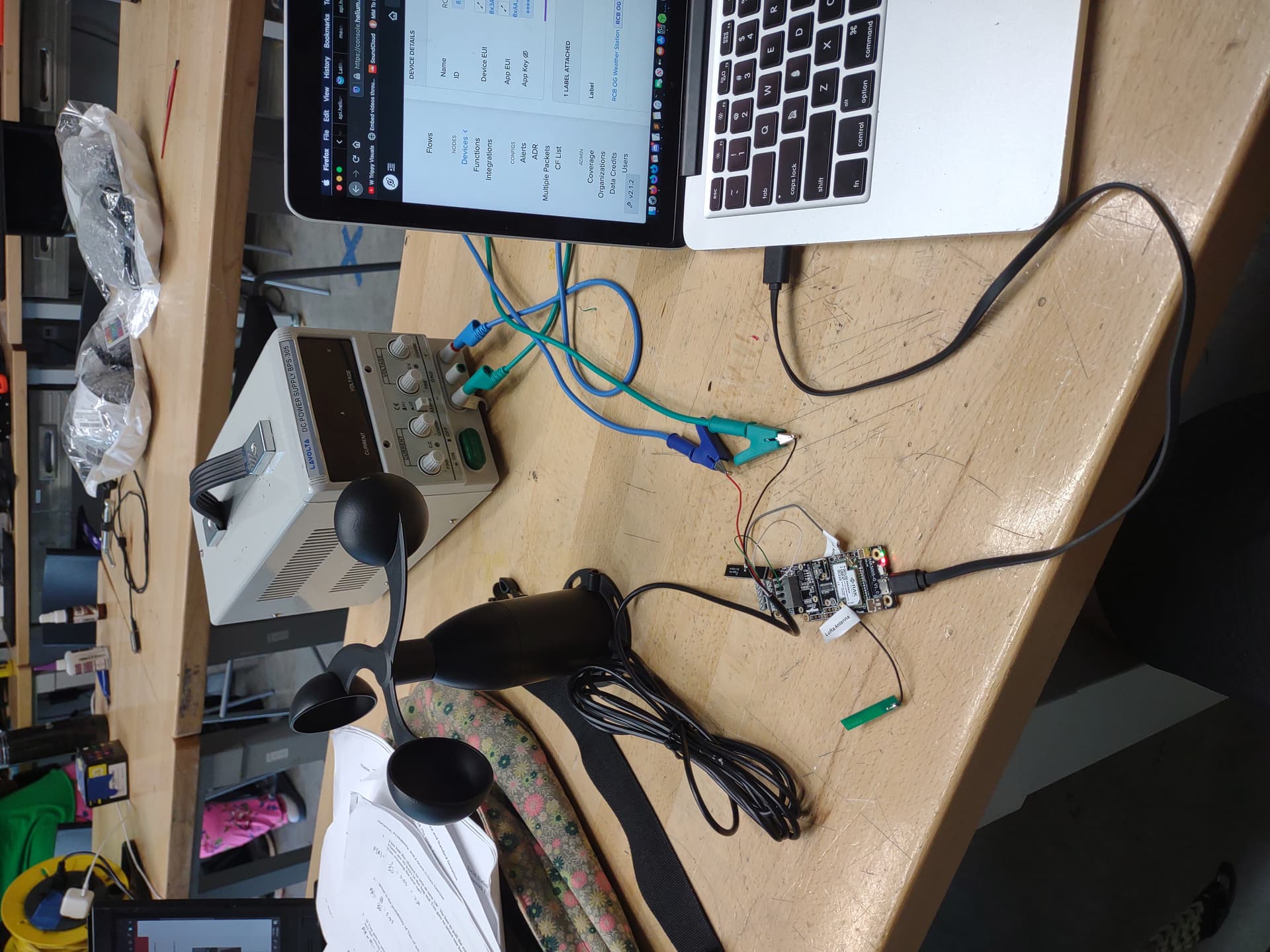

I plugged the wind sensor up to 9 volts and ran the code,I keep getting this error in my Arduino log.
Side question: there was a black and red wire, and green and white. Would the white go where the yellow wire did on the diagram you sent me a few posts up since it doesn’t have a yellow but has white and green?
Also is there any way to make the gas sensor read AQI instead of hms? I can’t seem to find anything about converting it!
Hi @a1projects ,
Failure in reading the registers might mean that the RS485 lines are broken. What current consumption does the sensor gets from the power supply? In your image the ground of the sensor is not attached to the ground of the WisBlock. Can you connect it and try again?
On the connection, exchanging green and white wont hurt since RS485 signals are differential. You can see if that will do the trick.
We are using Adafruit library in the example so there is no AQI. But you can try this code from Bosch itself BSEC-Arduino-library/basic.ino at master · BoschSensortec/BSEC-Arduino-library · GitHub.
.01 amps was what it said it was using. Where is the ground of the wisblock at? In the photo example they just had the black wire connected to the ground of the power supply
You can use the GND in the RAK5802 module.
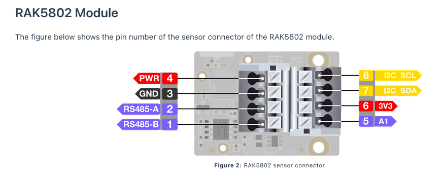
Theoretically, you do not need the ground since the lines are differential. But it won’t hurt ensuring that your ground potentials are at the same levels.
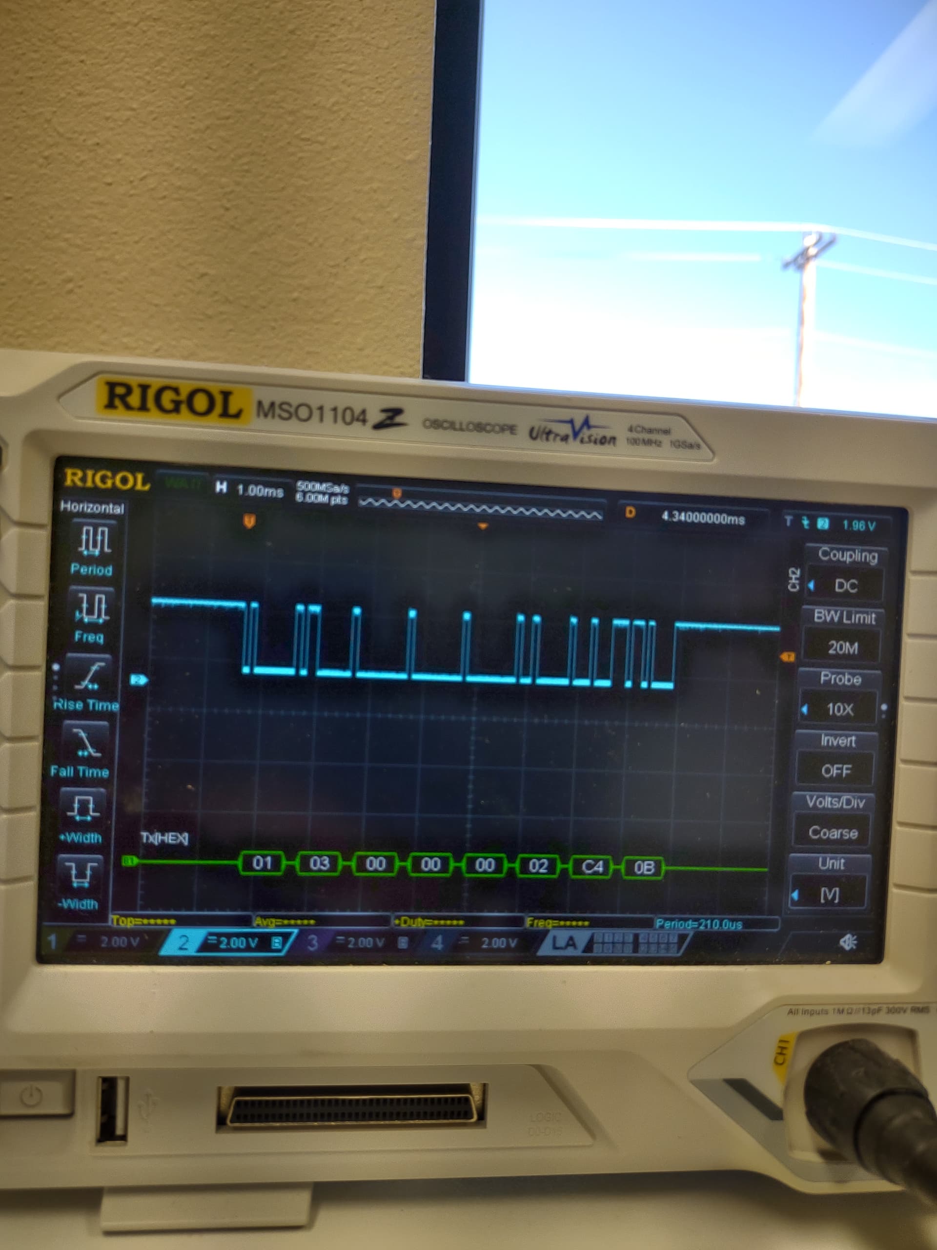
If you have an oscilloscope in your lab, you can also check the RS485 bus if any data is being transmitted.
I do have an oscilloscope, where would I use it though to check if the data is being transmitted? What part does it need to be in contact with?
This can be a good guide Decoding Sensor RS485 Output with an Oscilloscope | Life, The Universe and ... Everything! 
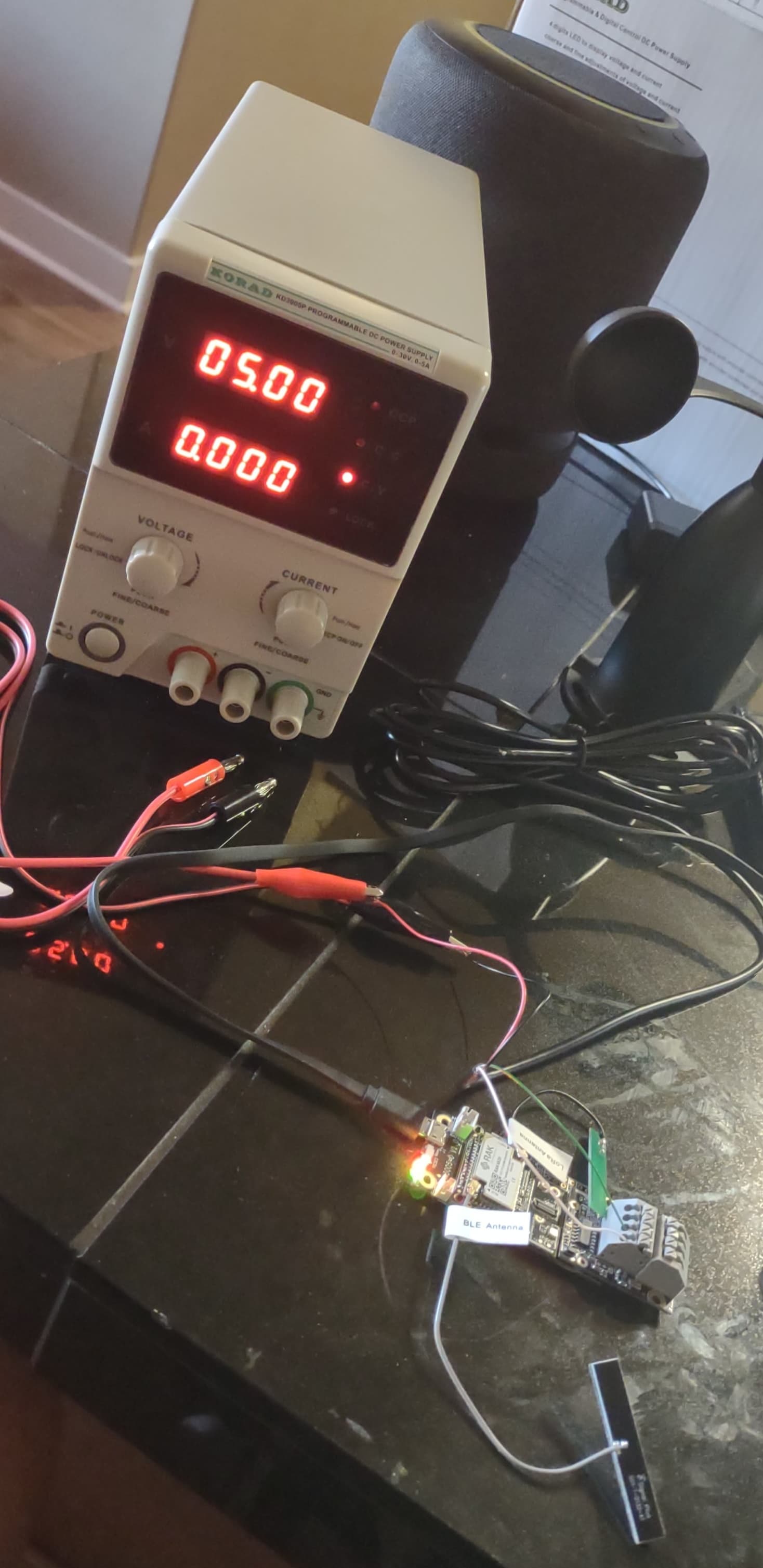
How many amps do I need to use with this? I got my power supply in. When I plug it in, it’s reading .02 amps at 5 volts
There is no legacy packet forwarding option on TTN anymore when registering the gateway, I put my device EUI in and it just says disconnected
Hi Sam,
With the Amps, are you referring to the current limit you need to set? 0.5A should be ok I think. If you see that you hit CC in any situation you can increase 0.5A slowly but I think 0.5A is already high.
With the gateway registration, you must use TTN V3 and not TTN V2. You cannot on-board gateways to TTN V2 anymore. Here’s the link for TTN V3 - https://cloud.thethings.network/
Please follow this guide how to onboard the gateway to TT V3 Updated tutorial for setup with TTN V3 / TTS? - #2 by Martin
What about the voltage, is 5 volts ok for the wind sensor? If not how many should I use? Ok thank you, I am going to try and configure it with this technique. Thank you! One issue I am having is that when I try to ssh back in the device is freezing up. Sometime I can get into the rak welcome terminal screen but can’t get past that and then other times I can’t even get that far. I tried restarting it but that didn’t fix the issue
I am not sure if 5V is ok. Can you confirm with the datasheet?
For the issue of terminal screen, is it for the gateway? Can you make a separate post regarding that so our gateway expert can support? Probably include some details or screenshots when it starts to freeze. I am using SSH on all my RPI gateways and all is fine except if I get disconnected to the network.
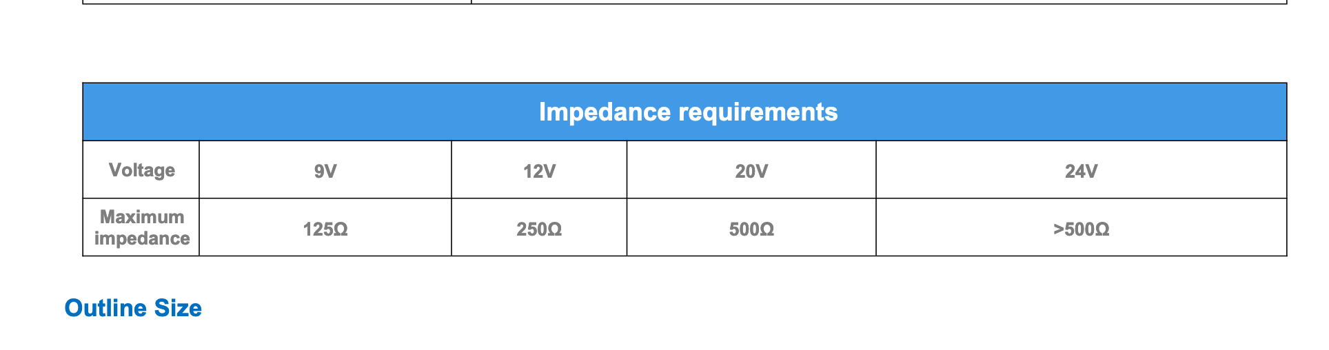
I am not sure which voltage to use, and why it has all these different increments. The power supply you recommended doesn’t even have a way to adjust resistance does it?
What would the payload for the scheduler .ino need to look like since it has both projects combined? I have this right now for the environment one, what do I need to add on to it to get all the data?
function Decoder(payload, port) {
    if(payload[0] === 0x01) {
        return [
            {
                field: "TEMPERATURE",
                value: (payload[1] << 8 | payload[2]) / 100
            },
            {
                field: "HUMIDITY",
                value: (payload[3] << 8 | + payload[4]) / 100
            },
            {
                field: "PRESSURE",
                value: (payload[8] | (payload[7] << 8) | (payload[6] << 16) | (payload[5] << 24)) / 100
            },
            {
                field: "GAS",
                value: payload[12] | (payload[11] << 8) | (payload[10] << 16) | (payload[9] << 24)
            },
            {
                field: "COUNTER",
                value: payload[16] | (payload[15] << 8) | (payload[14] << 16) | (payload[13] << 24)
            }
        ];
    }
    if(payload[0] === 0x02) {
        return [
            {
                field: "TEMPERATURE",
                value: (payload[1] << 8 | payload[2]) / 100
            },
            {
                field: "HUMIDITY",
                value: (payload[3] << 8 | + payload[4]) / 100
            },
            {
                field: "COUNTER",
                value: payload[8] | (payload[7] << 8) | (payload[6] << 16) | (payload[5] << 24)
            }
        ];
    }
    if(payload[0] === 0x03) {
        return [
            {
                field: "LIGHT",
                value: (payload[4] | (payload[3] << 8) | (payload[2] << 16) | (payload[1] << 24)) / 100
            },
            {
                field: "COUNTER",
                value: payload[8] | (payload[7] << 8) | (payload[6] << 16) | (payload[5] << 24)
            }
        ];
    }
    if(payload[0] === 0x04) {
        return [
            {
                field: "COUNTER",
                value: payload[4] | (payload[3] << 8) | (payload[2] << 16) | (payload[1] << 24)
            }
        ];
    }
}
Any idea beegee maybe on this payload build?
Ok now that I have gotten the device connected to the network again, I am noticing the weather station scheduler script is the only one not working now. It stays at this below for both Helium and TTN
=====================================
Welcome to RAK4630 LoRaWan!!!
Type: OTAA
Region: US915
=====================================
Welcome to RAK4630 LoRaWan!!!
Type: OTAA
Region: US915
Carl are you sure this wind sensor you recommended works with this rak 4630 board?
https://www.lcsc.com/product-detail/Specialized-Sensors_Ubibot-JXBS-3001-FS_C843317.html
That wind sensor has the same PN as what we used on the solution example so that will work.
Also, any wind sensor will work with RAK4630 as long as you can get its data.
We were able to send it data and verified that it was the same as the datasheet and the sensor never responds back. We verified from the datasheet you sent me here on the oscilliscope as you can see, and the sensor does not respond.
Wind Sensor Data Sheet
Hi carlrowan, I am using rak4631 to send data to the gateway through lora. I have a little doubt about Lora transmission interval. The default is #define LORAWAN_APP_INTERVAL 20000. But I want to know what is the minimum value that can be set?
Please don’t hijack existing threads. This is a new question and should be in a new thread.