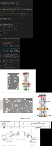
Hi, I have been having issues while integrating the Ethernet and CAN module over SPI
I am using the following hardware :
RAK13800 (Ethernet Module), RAK13006(CANBus Interface),RAK11200/RAK11200-C(ESP32), RAK19016 (Power Slot Module),RAK19011(Dual IO Baseboard)
The issues that I am facing are as follows:-
-
On directly connecting the CAN and Ethernet modules with the Baseboard and using the default libraries provided , none of the given work. Only one module works at a time.
-
On checking the libraries source files, the slave select pin on both the CAN(RAK_CAN.h) and Ethernet(w5100.h) was set to pin 10 which was causing the issue in communication.
-
On referring to the schematic of RAK13800(Ethernet Module), 2 SPI_CS were present (pin 25 and 37), now pin 37 for the CAN module is for INT0 (STBY pin of CAN transceiver MCP2518FDT-E/SL). The STBY pin of the transceiver works on Active low same as the SPI Chip select thereby eliminating the choice of using pin 37 as the SPI SS pin in W5100.h library.
-
Now referring to the schematic of RAK13006(CAN Interface Module) it is shown that there are 3 SPI_CS pins(pin 20, 25 &31 of the 40pin connector) . Here the pin 25 CS is currently being used, pin 31 is used as reset on the Ethernet module, leaving pin 20 to be used as CS . Pin 20 being currently assigned as generic IO or i2c clock.
The WisBlock 40 pin connector schematic is not present for the CAN module(RAK13006).
So can we used pin 20 as CS for the CAN module? And what would be the corresponding pin number to be added in the RAK_CAN.h library as chip select for the same?

