Hello Beegee,
Can you help me solve this problem?
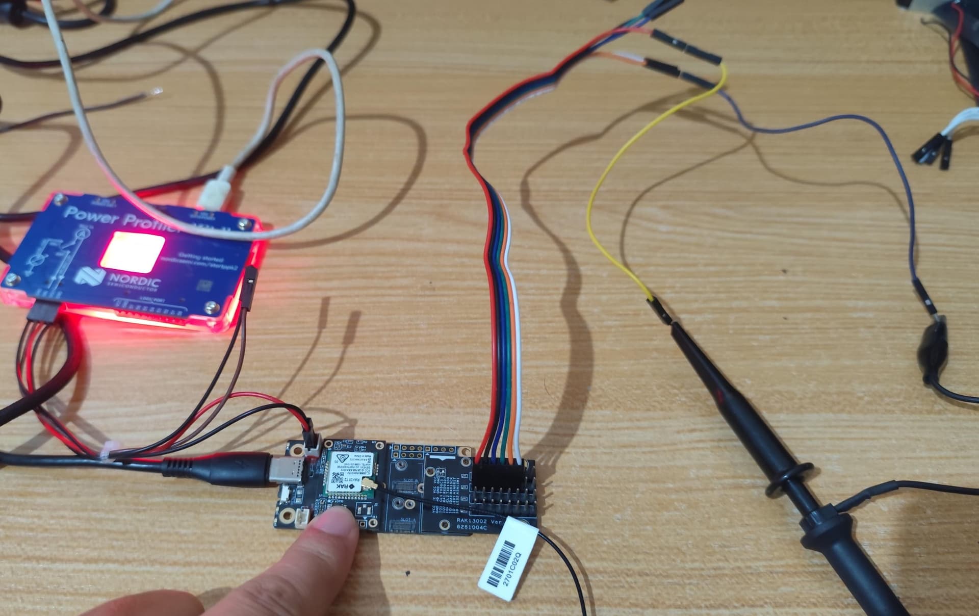
Hardware: RAK3372 (RAK3172-based WisBlock Core) on a WisBlock base board, RAK13002 IO breakout module in the IO slot, RXD1/TXD1 wired to an external UART sensor (A01NYUB ultrasonic distance sensor, 9600-8-N-1, TX-only). Sensor VCC is powered through the header’s VCC pin, reworked so it follows 3V3_S (moved the 0R resistor from the R1 pads to the R2 pads) so it can be switched by WB_IO2.
Firmware: RUI_4.2.4_RAK3172-E
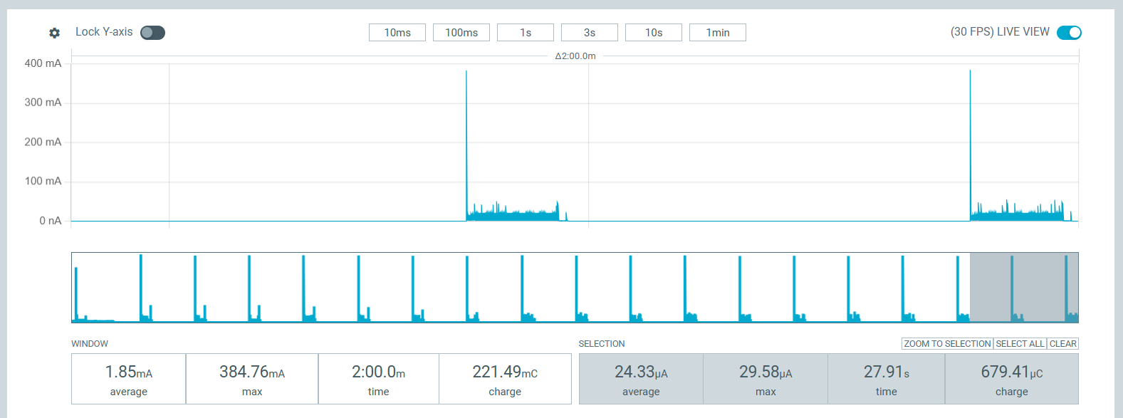
Summary: with the sensor’s VCC correctly switched off via WB_IO2/3V3_S during sleep, the module still draws far more current than expected while asleep, because current appears to leak backward into the unpowered sensor through the RXD1 data line.
Measurements (isolating the sleep current specifically, not counting LoRa TX):
| Condition | Sleep current |
|—|—|
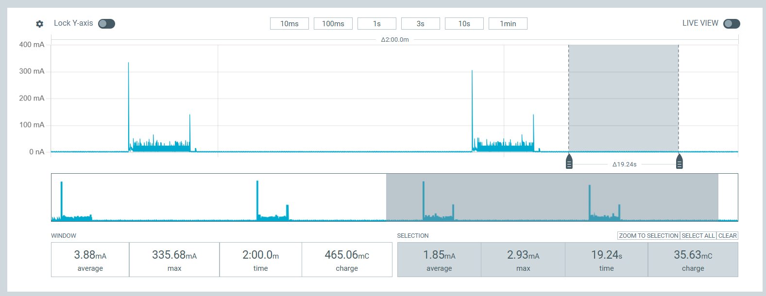
| Same firmware/code, run on a RAK4631 instead (nRF52840) | 24.33uA avg / 29.58uA max - clean, as expected |
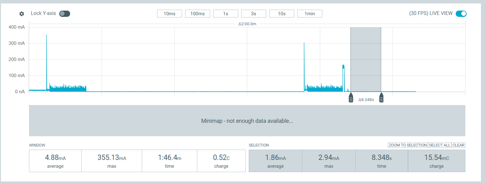
| RAK3372, sensor wired normally, Serial1.end() called after each read | 2.05mA |
| RAK3372, sensor wired normally, + pinMode(PIN_SERIAL1_RX, OUTPUT); digitalWrite(PIN_SERIAL1_RX, LOW); after Serial1.end() | 234uA |
| RAK3372, same as above but sensor’s GND wire physically disconnected | 20.04uA |
| RAK3372, same as above but Serial1/RXD1 data wire physically disconnected | 20.04uA |
| RAK3372, api.system.lpmlvl.set(1) (Stop1) instead of set(2) (Stop2), sensor wired normally | no improvement over the 234uA case |
Interpretation: disconnecting either GND or the RXD1 data line (but leaving the sensor’s VCC switched off either way) drops current to the expected ~20uA baseline. This points to a current path through RXD1 into the sensor’s input protection circuitry while VCC is at 0V - classic “phantom powering” through a signal line. Forcing PIN_SERIAL1_RX LOW as a plain GPIO after Serial1.end() reduces it by ~90% (2.05mA → 234uA) but doesn’t eliminate it, so some residual pull/leak remains that we can’t reach from the RUI3 Arduino API.
We also checked AT+LPMLVL’s own documentation, which states Stop2 “will not allow you to wake up using UART1” (unlike Stop1) - we hypothesized this might leave UART1’s pins in a less-defined state during Stop2, but switching to Stop1 (api.system.lpmlvl.set(1)) made no measurable difference to the 234uA leak.
Questions:
-
Is there a lower-level/documented way to fully release UART1’s RX pin (no pull, guaranteed 0V, or true Hi-Z) after
Serial1.end()on RAK3172, beyond whatpinMode()/digitalWrite()from the Arduino API can reach? -
Is this related to the changelog note from v3.4.2, “RUI-345: TX1 used as recovery pin causes problems on RAK3172/RAK4631 if a module is used that uses RX1/TX1”? Could the recovery-pin function be the source of the residual leak?
-
Is a GND-side (low-side) switch for the sensor, instead of/in addition to the existing VCC-side (3V3_S) switch, the recommended approach for RAK3172 in this situation, or is there a cleaner fix?
/**
 * @file RUI3-RAK-A01NYUB-UART.ino
 * @brief RUI3 low power node reading distance from an A01NYUB UART ultrasonic sensor
 * @version 0.1
 * @date 2026-09-26
 *
 * @copyright Copyright (c) 2026
 *
 */
#include "app.h"

/** Packet is confirmed/unconfirmed (Set with AT commands) */
bool g_confirmed_mode = false;
/** If confirmed packet, number or retries (Set with AT commands) */
uint8_t g_confirmed_retry = 0;
/** Data rate  (Set with AT commands) */
uint8_t g_data_rate = 3;

/** Flag if transmit is active, used by some sensors */
volatile bool tx_active = false;

/** fPort to send packages */
uint8_t set_fPort = 2;

/** Payload buffer */
uint8_t g_solution_data[64];

uint16_t my_fcount = 1;

/**
 * @brief Callback after join request cycle
 *
 * @param status Join result
 */
void joinCallback(int32_t status)
{
	if (status != 0)
	{
		MYLOG("JOIN-CB", "LoRaWan OTAA - join fail! \r\n");
		// To be checked if this makes sense
		// api.lorawan.join();
	}
	else
	{
		MYLOG("JOIN-CB", "LoRaWan OTAA - joined! \r\n");
		digitalWrite(LED_BLUE, LOW);
	}
}

/**
 * @brief LoRaWAN callback after packet was received
 *
 * @param data pointer to structure with the received data
 */
void receiveCallback(SERVICE_LORA_RECEIVE_T *data)
{
	MYLOG("RX-CB", "RX, port %d, DR %d, RSSI %d, SNR %d", data->Port, data->RxDatarate, data->Rssi, data->Snr);
	for (int i = 0; i < data->BufferSize; i++)
	{
		Serial.printf("%02X", data->Buffer[i]);
	}
	Serial.print("\r\n");
	tx_active = false;
}

/**
 * @brief Callback for LinkCheck result
 *
 * @param data pointer to structure with the linkcheck result
 */
void linkcheckCallback(SERVICE_LORA_LINKCHECK_T *data)
{
	MYLOG("LC_CB", "%s Margin %d GW# %d RSSI%d SNR %d", data->State == 0 ? "Success" : "Failed",
		  data->DemodMargin, data->NbGateways,
		  data->Rssi, data->Snr);
}

/**
 * @brief LoRaWAN callback after TX is finished
 *
 * @param status TX status
 */
void sendCallback(int32_t status)
{
	MYLOG("TX-CB", "TX status %d", status);
	digitalWrite(LED_BLUE, LOW);
	tx_active = false;
}

/**
 * @brief LoRa P2P callback if a packet was received
 *
 * @param data pointer to the data with the received data
 */
void recv_cb(rui_lora_p2p_recv_t data)
{
	MYLOG("RX-P2P-CB", "P2P RX, RSSI %d, SNR %d", data.Rssi, data.Snr);
	for (int i = 0; i < data.BufferSize; i++)
	{
		Serial.printf("%02X", data.Buffer[i]);
	}
	Serial.print("\r\n");
	tx_active = false;
}

/**
 * @brief LoRa P2P callback if a packet was sent
 *
 */
void send_cb(void)
{
	MYLOG("TX-P2P-CB", "P2P TX finished");
	digitalWrite(LED_BLUE, LOW);
	tx_active = false;
}

/**
 * @brief LoRa P2P callback for CAD result
 *
 * @param result true if activity was detected, false if no activity was detected
 */
void cad_cb(bool result)
{
	MYLOG("CAD-P2P-CB", "P2P CAD reports %s", result ? "activity" : "no activity");
}

/**
 * @brief Arduino setup, called once after reboot/power-up
 *
 */
void setup()
{
	// Setup for LoRaWAN
	if (api.lorawan.nwm.get() == 1)
	{
		g_confirmed_mode = api.lorawan.cfm.get();

		g_confirmed_retry = api.lorawan.rety.get();

		g_data_rate = api.lorawan.dr.get();

		// Setup the callbacks for joined and send finished
		api.lorawan.registerRecvCallback(receiveCallback);
		api.lorawan.registerSendCallback(sendCallback);
		api.lorawan.registerJoinCallback(joinCallback);
		api.lorawan.registerLinkCheckCallback(linkcheckCallback);
	}
	else // Setup for LoRa P2P
	{
		api.lora.registerPRecvCallback(recv_cb);
		api.lora.registerPSendCallback(send_cb);
		api.lora.registerPSendCADCallback(cad_cb);
	}

	pinMode(LED_GREEN, OUTPUT);
	digitalWrite(LED_GREEN, HIGH);
	pinMode(LED_BLUE, OUTPUT);
	digitalWrite(LED_BLUE, HIGH);

	// WB_IO2 (== A01NYUB_PWR, see app.h) switches the 3V3_S rail that powers
	// the sensor. It's configured and toggled by init_a01nyub()/read_a01nyub(),
	// nothing to do here.

	// Start Serial
	Serial.begin(115200);

	// Delay for 5 seconds to give the chance for AT+BOOT
	delay(5000);

	api.system.firmwareVersion.set("RUI3-A01NYUB-UART-V1.0.0");

	Serial.println("RAKwireless RUI3 Node");
	Serial.println("------------------------------------------------------");
	Serial.println("Setup the device with WisToolBox or AT commands before using it");
	Serial.printf("Version %s\n", api.system.firmwareVersion.get().c_str());
	Serial.println("------------------------------------------------------");

	// Initialize module
	Wire.begin();

	// Initialize the A01NYUB UART distance sensor (this also powers it down
	// again once the check read is done)
	has_a01nyub = init_a01nyub();

	// Register the custom AT command to get device status
	if (!init_status_at())
	{
		MYLOG("SETUP", "Add custom AT command STATUS fail");
	}

	// Register the custom AT command to set the send interval
	if (!init_interval_at())
	{
		MYLOG("SETUP", "Add custom AT command Send Interval fail");
	}

	// Get saved sending interval from flash
	get_at_setting();

	digitalWrite(LED_GREEN, LOW);

	// Create a timer.
	api.system.timer.create(RAK_TIMER_0, sensor_handler, RAK_TIMER_PERIODIC);
	if (custom_parameters.send_interval != 0)
	{
		// Start a timer.
		api.system.timer.start(RAK_TIMER_0, custom_parameters.send_interval, NULL);
	}

	// Check if it is LoRa P2P
	if (api.lorawan.nwm.get() == 0)
	{
		digitalWrite(LED_BLUE, LOW);

		sensor_handler(NULL);
	}

	if (api.lorawan.nwm.get() == 1)
	{
		if (g_confirmed_mode)
		{
			MYLOG("SETUP", "Confirmed enabled");
		}
		else
		{
			MYLOG("SETUP", "Confirmed disabled");
		}

		MYLOG("SETUP", "Retry = %d", g_confirmed_retry);

		MYLOG("SETUP", "DR = %d", g_data_rate);
	}

	// Enable low power mode
#if defined(_VARIANT_RAK3172_) || defined(_VARIANT_RAK3172_SIP_)
	/// \todo REQUIRES BSP VERSION 4.2.1
	// Tried Stop1 (level 1) hoping it would leave UART1 in a cleaner state
	// and avoid the phantom-power leak into the sensor (see a01nyub.cpp) -
	// measured, it made no difference, so stick with Stop2 for the lower
	// base current. The leak is a separate issue, see the GND-side MOSFET
	// note in a01nyub.cpp / the forum report.
	api.system.lpmlvl.set(2);
#endif
	api.system.lpm.set(1);

	// If available, enable BLE advertising for 30 seconds and open the BLE UART channel
#if defined(_VARIANT_RAK3172_) || defined(_VARIANT_RAK3172_SIP_)
// No BLE
#else
	Serial6.begin(115200, RAK_AT_MODE);
	api.ble.advertise.start(30);
#endif
}

/**
 * @brief sensor_handler is a timer function called every
 * custom_parameters.send_interval milliseconds. Default is 120000. Can be
 * changed with ATC+SENDINT command
 *
 */
void sensor_handler(void *)
{
	MYLOG("UPLINK", "Start");
	digitalWrite(LED_BLUE, HIGH);

	if (api.lorawan.nwm.get() == 1)
	{
		// Check if the node has joined the network
		if (!api.lorawan.njs.get())
		{
			MYLOG("UPLINK", "Not joined, skip sending");
			return;
		}
	}

	// Power up the sensor just for the measurement (A01NYUB_PWR, not WB_IO2,
	// since the RAK13002 header's VCC pin can't be switched off, see app.h)
	digitalWrite(A01NYUB_PWR, HIGH);
	delay(500); // let the sensor boot and start streaming

	// Read the A01NYUB sensor for A01NYUB_READ_WINDOW_MS (10s) and average
	// the valid samples, then add the result to the payload (Cayenne LPP
	// analog input, channel 1, in the first 4 bytes of g_solution_data).
	// This call blocks for ~10s, so the full measurement + send cycle takes
	// roughly 10.5s plus the LoRa airtime.
	bool got_reading = read_a01nyub(true);

	// Power down the sensor again, reading is done
	digitalWrite(A01NYUB_PWR, LOW);

	if (!got_reading)
	{
		MYLOG("UPLINK", "Sensor read failed, skip sending");
		digitalWrite(LED_BLUE, LOW);
		return;
	}

	// Send the packet
	send_packet();
}

/**
 * @brief Send the data packet that was prepared in
 * Cayenne LPP format by the different sensor and location
 * aqcuision functions
 *
 */
void send_packet(void)
{
	// Check if it is LoRaWAN
	if (api.lorawan.nwm.get() == 1)
	{
		MYLOG("UPLINK", "Sending packet # %d", my_fcount);
		my_fcount++;
		// Send the packet
		if (api.lorawan.send(4, g_solution_data, set_fPort, g_confirmed_mode, g_confirmed_retry))
		{
			MYLOG("UPLINK", "Packet enqueued, size 4");
			tx_active = true;
		}
		else
		{
			MYLOG("UPLINK", "Send failed");
			tx_active = false;
		}
	}
	// It is P2P
	else
	{
		MYLOG("UPLINK", "Send packet with size 4 over P2P");

		digitalWrite(LED_BLUE, LOW);

		if (api.lora.psend(4, g_solution_data, false))
		{
			MYLOG("UPLINK", "Packet enqueued");
		}
		else
		{
			MYLOG("UPLINK", "Send failed");
		}
	}
}

/**
 * @brief This example is complete timer driven.
 * The loop() does nothing than sleep.
 *
 */
void loop()
{
	api.system.sleep.all();
}
/**
 * @file a01nyub.cpp
 * @brief Initialization and reading of the A01NYUB UART ultrasonic distance sensor
 * @version 0.1
 * @date 2026-09-26
 *
 * @copyright Copyright (c) 2026
 *
 * A01NYUB wiring (3 wires, sensor only transmits, no RX needed):
 *   Red    -> RAK13002 header's VCC pin, AFTER reworking the board so VCC
 *             follows the switched 3V3_S rail instead of the fixed 3V3 rail
 *             (move the 0R resistor from the R1 pads to the R2 pads - see
 *             app.h for details). This lets WB_IO2 (A01NYUB_PWR) power the
 *             sensor fully off between readings.
 *   Black  -> GND
 *   Yellow -> RXD1 of the WisBlock IO slot UART (Serial1 RX)
 *
 * Protocol: the sensor continuously streams 4 byte frames at 9600-8-N-1:
 *   [0] 0xFF          frame header
 *   [1] Data_H        distance high byte
 *   [2] Data_L        distance low byte
 *   [3] Checksum      low byte of (Header + Data_H + Data_L)
 * Distance = (Data_H << 8) | Data_L, in millimeters.
 */
#include "app.h"

bool has_a01nyub = false;
uint16_t last_distance_mm = 0;

/**
 * @brief Power up the sensor and its UART, then take one measurement
 *        to confirm it is connected.
 *
 * @return true if a valid frame was received
 * @return false if no sensor answered in time
 */
bool init_a01nyub(void)
{
	pinMode(A01NYUB_PWR, OUTPUT);
	digitalWrite(A01NYUB_PWR, HIGH);

	// Give the sensor time to boot and start streaming
	delay(500);

	has_a01nyub = read_a01nyub(false);
	if (!has_a01nyub)
	{
		MYLOG("A01", "No valid frame received, assuming no sensor connected");
	}

	digitalWrite(A01NYUB_PWR, LOW);

	return has_a01nyub;
}

/**
 * @brief Try to read a single distance frame from the A01NYUB sensor.
 *
 * @param distance_mm output, distance in mm if a valid frame was read
 * @return true a valid frame with a correct checksum was read
 * @return false timeout or checksum error
 */
static bool read_single_frame(uint16_t *distance_mm)
{
	// Drop any stale bytes so we sync on a fresh frame
	while (A01NYUB_UART.available())
	{
		A01NYUB_UART.read();
	}

	uint8_t frame[4] = {0};
	uint32_t start_time = millis();
	bool got_header = false;
	uint8_t idx = 0;

	while ((millis() - start_time) < A01NYUB_FRAME_TIMEOUT_MS)
	{
		if (A01NYUB_UART.available())
		{
			uint8_t rx_byte = A01NYUB_UART.read();
			if (!got_header)
			{
				if (rx_byte == A01NYUB_HEADER)
				{
					got_header = true;
					frame[0] = rx_byte;
					idx = 1;
				}
				// else keep looking for the header byte
			}
			else
			{
				frame[idx++] = rx_byte;
				if (idx == 4)
				{
					break;
				}
			}
		}
	}

	if (idx != 4)
	{
		MYLOG("A01", "Timeout waiting for sensor frame");
		return false;
	}

	uint8_t checksum = (frame[0] + frame[1] + frame[2]) & 0xFF;
	if (checksum != frame[3])
	{
		MYLOG("A01", "Checksum mismatch, got %02X expected %02X", frame[3], checksum);
		return false;
	}

	uint16_t reading = (frame[1] << 8) | frame[2];

	if ((reading < A01NYUB_MIN_RANGE_MM) || (reading > A01NYUB_MAX_RANGE_MM))
	{
		MYLOG("A01", "Distance %d mm out of sensor range", reading);
		return false;
	}

	*distance_mm = reading;
	return true;
}

/**
 * @brief Read the A01NYUB sensor for A01NYUB_READ_WINDOW_MS (10s by default),
 *        collecting every valid frame, and return the average distance.
 *        Averaging over several seconds smooths out single-frame noise from
 *        the ultrasonic reading.
 *
 * @param add_payload if true, add the averaged distance as a Cayenne LPP
 *                     analog input (channel 1, type 0x02, 0.01 resolution,
 *                     unit meter) to g_solution_data
 * @return true at least one valid frame was read and averaged
 * @return false no valid frame was read during the whole window
 */
bool read_a01nyub(bool add_payload)
{
	// On the RAK3172 core, UART1 in RAK_CUSTOM_MODE comes back in a broken
	// state after the MCU has been through api.system.sleep.all() at least
	// once - re-opening it fresh before every read cycle works around that.
	A01NYUB_UART.end();
	A01NYUB_UART.begin(A01NYUB_BAUD, RAK_CUSTOM_MODE);
	delay(50);

	uint32_t sum_mm = 0;
	uint16_t valid_samples = 0;
	uint16_t total_samples = 0;

	uint32_t window_start = millis();
	while ((millis() - window_start) < A01NYUB_READ_WINDOW_MS)
	{
		uint16_t reading_mm = 0;
		total_samples++;
		if (read_single_frame(&reading_mm))
		{
			sum_mm += reading_mm;
			valid_samples++;
		}
	}

	MYLOG("A01", "Got %d valid samples out of %d in %d ms", valid_samples, total_samples, A01NYUB_READ_WINDOW_MS);

	// Close the UART again so its peripheral clock doesn't block the MCU
	// from reaching its deepest sleep state between reading cycles.
	A01NYUB_UART.end();

	// With the sensor's VCC cut, RXD1 is still wired to the sensor's TX pin.
	// If that pin keeps an internal pull-up (left over from the UART
	// peripheral) it can back-feed the unpowered sensor through its input
	// protection diodes, drawing mA-range "phantom power" through the data
	// line even though VCC reads 0V. Force it to a driven LOW plain GPIO so
	// there is no voltage left on that line for the sensor to leak from.
	pinMode(PIN_SERIAL1_RX, OUTPUT);
	digitalWrite(PIN_SERIAL1_RX, LOW);

	if (valid_samples == 0)
	{
		MYLOG("A01", "No valid samples, giving up");
		return false;
	}

	uint16_t distance_mm = sum_mm / valid_samples;

	last_distance_mm = distance_mm;
	MYLOG("A01", "Average distance is %d mm", distance_mm);

	if (add_payload)
	{
		// Cayenne LPP analog input, channel 1, 0.01 resolution => value in meters
		int16_t value = (int16_t)((distance_mm / 1000.0) * 100);
		g_solution_data[0] = 1;	  // channel
		g_solution_data[1] = 0x02; // LPP analog input type
		g_solution_data[2] = (uint8_t)(value >> 8);
		g_solution_data[3] = (uint8_t)(value & 0xFF);
	}

	return true;
}
RAK4631 power consumption capture
RAK3372 power consumption capture