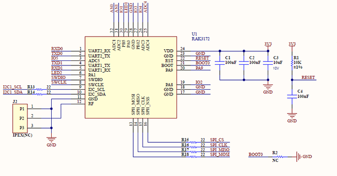
well if I checked the schematic on rak3372 there is a resistor which is R2 between Boot0 and GND. although there is NC ( i think "N"ot "C"onnected) mark. I measured and it show 4.1k . why boot0 need this. should we add our schematic for new PCB?
This is not meant as a resistor, more like a bridge that allows you to pull BOOT0 to GND.
BOOT0 pulled to GND is required when you want to flash with the STM32CubeIDE Programmer.
Otherwise you can leave it open.
RUI3 does not need BOOT0 to flash a new firmware.
To be flexible in the future, you can add BOOT0 and GND close to each other as solder pads or a jumper in your PCB.
So if I removed R2 on board now, I cant flash with stm programmer, isnt it? sometimes rak3172 can not respond AT commands so I am flashing with stm programmer. if r2 was not here, I can not?
“If that’s the case, the R2 resistor is very important, and I believe it is essential to have it on the PCB.”
For me the SWD interface is more important than the BOOT0 pin accessible.
With JLink I can flash the device independent of the status of the BOOT0 pin.
This topic was automatically closed 10 days after the last reply. New replies are no longer allowed.
