WisBlock LEDs aren´t responding commands

Hi,

I am testing the 3 builtin LED in the board 5005-O with a simple library, but they aren´t responding the command digitalWrite.

Well first question is:
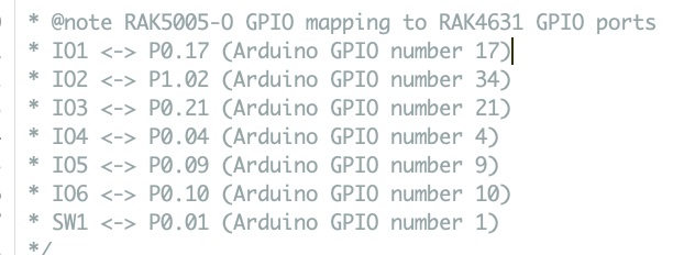
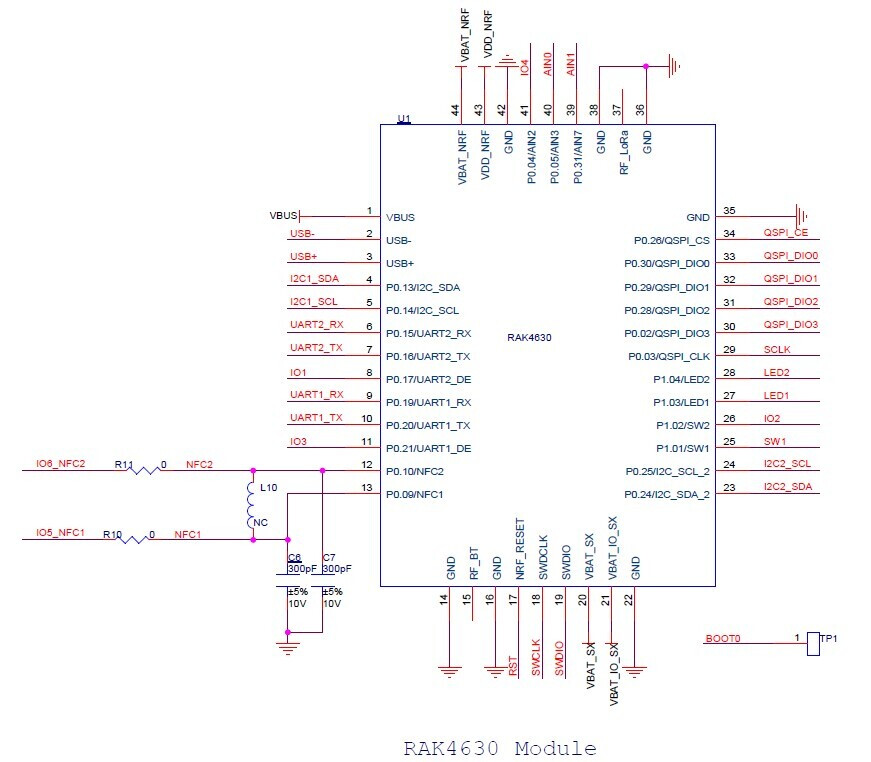
Are the right pins: RED-14, GREEN-15 and BLUE-16? I already read the Core documentation and the PIN number 14, 15 and 16 I toke from there.

Could you help me?

The files are:

Main.cpp

#include <Arduino.h>
#include <LEDsInit.h>

int RecPinR = 14, RecPinG = 15, RecPinB = 16;

void setup()
{
    LEDsInterface LED(RecPinR, RecPinG, RecPinB);
    LED.LEDsInit();
};

void loop() 
{  
};

LEDsInit.h

/*
 * Lib name: LEDsInit.h
 * purpose : create a clear vision in the code when all serial interface inialization routine is move to this lib
 * author  : Claudio Rosa
 * contact : https://www.linkedin.com/in/claudio-rosa-aa71a418
 * date    : 30/01/2021
 */

#ifndef LED_ini
#define LED_ini

class LEDsInterface
{
    private:
        int pinR, pinG, pinB;
    public:
            LEDsInterface(int RecPinR, int RecPinG,int RecPinB);
            int getPins();
            void setPins(int RecPinR, int RecPinG,int RecPinB);
            void LEDsInit();
};
#endif

LEDsInit.cpp

/*
 * Lib name: LEDsInit.h
 * purpose : create a clear vision in the code when all serial interface inialization routine is move to this lib
 * author  : Claudio Rosa
 * contact : https://www.linkedin.com/in/claudio-rosa-aa71a418
 * date    : 30/01/2021
 */

#include <LEDsInit.h>
#include <Arduino.h>

LEDsInterface::LEDsInterface(int RecPinR, int RecPinG,int RecPinB)
{
    setPins(RecPinR, RecPinG, RecPinB);
};

void LEDsInterface::setPins(int RecPinR, int RecPinG,int RecPinB)
{
    pinR = RecPinR;
    pinG = RecPinG;
    pinB = RecPinB;
};

int LEDsInterface::getPins()
{
return pinR, pinG, pinB;
};

void LEDsInterface::LEDsInit()
{   
    getPins();
  
    pinMode(pinR, OUTPUT);
    pinMode(pinG, OUTPUT);
    pinMode(pinB, OUTPUT);

    int i = 1;

    while (i <= 3)
        {
        digitalWrite(pinR, LOW);
        Serial.println("LED RED PIN=" + String(pinR) + "=> OFF");
        delay(1000);

        digitalWrite(pinG, LOW);
        Serial.println("LED GREEN PIN=" + String(pinG) + "=> OFF");
        delay(1000);

        digitalWrite(pinB, LOW);
        Serial.println("LED BLUE PIN=" + String(pinB) + "=> OFF");
        delay(1000);

        digitalWrite(pinR, HIGH);
        Serial.println("LED RED PIN=" + String(pinR) + "=> ON");
        delay(1000);

        digitalWrite(pinG, HIGH);
        Serial.println("LED GREEN PIN=" + String(pinG) + "=> ON");
        delay(1000);

        digitalWrite(pinB, HIGH);
        Serial.println("LED BLUE PIN=" + String(pinB) + "=> ON");
        delay(1000);

        ++i;
        };

    Serial.println("======================================");   
    Serial.println("= LEDS RED, GREEN and BLUE initialized");
    Serial.println("======================================");
};

Hi @crmrosa,

From RAK5005-O documentation

RED pin is for charging so it is not configurable.
In arduino codes,
GREEN should be defined as 35
BLUE should be defined as 36

The numbers (14,15,16) you are looking at are the names for the WisBlock connector.

I will take note of this and update the documentation.

Other pins you might be interested is on the example sketches of RAK4631.

image

Btw, I updated the formatting of your code to be read easily. Also, you can remove the semicolon on your C/C++ codeblocks. They are not needed.

You are correct, I was looking for the pin number in the wrong place, I mean in the WisCore connector.

But at the same time, the Core datasheet LED1-27 and LED2-28: https://docs.rakwireless.com/Product-Categories/WisBlock/RAK4631/Datasheet/

But the problem is: who is LED1 and LED2? If RED LED can´t be configured, I suppose that they are LED1-Green and LED2-Blue.
What is not clear it is that in the Base Board datasheet, the LEDs are called LED1-14, LED2-15 and LED2-16: RAK5005-O WisBlock Base Board Datasheet | RAKwireless Documentation Center

I think that these documentations are mixing the LED´s names. Could you help me to clarify who is LED1, LED2 and LED3?

I tested and it is working fine with LED Green - 35 and LED Blue - 36.

Where did you find these PINs documentation? The Core datasheet is shown PINs 27 and 28.

I got it from example sketches. Those pins are defined on top of the LoRaWAN_OTAA example of RAK4631.

The pins of RAK4630/RAK4631 don’t correspond to the Arduino pins. That BSP is based on Adafruit nRF52 BSP. More references here Installation of Board Support Package in Arduino IDE | RAKwireless Documentation Center

I will update the docs to make those clear. Thanks for pointing out :+1:

More about the pins, on the lower port of NRF52 P0.xx, those pins followed the Arduino pins.

Like for P0.17 (IO1 of wisblock) that is Arduino GPIO 17 or P0.21 (IO3 of wisblock) that is Arduino GPIO21.

But for LEDs, they are different because they are on higher port P1.xx.

1 Like

@carlrowan and @beegee

Thank you by your support.

As I bought some WisBlocks boards, Core and Sensor, I am working to create reduction on number of C++ line codes in the main.cpp for basic routines like initialization for: Sensor, LEDs, USB ports, LoRa radios. I mean, most of iniatization and tests routines, I am creating initialization libraries, based on the codes the Beegee already did.

My intention is to be sure that most of routine procedures will act behind the scene, I mean that the user will pay attention with really it is really the mission. For example, a temperature sensor that it has a LoRa radio to transmit the temperature measured and in a connection failure to LoRa network, it need to recover/re-join itself without to press the “reset button” :slight_smile:

When I have a more mature code, I would like to share with you. I forgot to mention that I working with VSCode and PlatformIO.

Have a nice Carnaval! :slight_smile:

1 Like

Hi @carlrowan, @beegee , @jmarcelino ,

It is not finished yet, I mean I am working on it, but I already did a version based on the examples the beegee did.

What I did it was to move the operation for each board Sensors and IO, for a owns library. It is a draft yet, but I am working to create a version with RAK4640,RAK1906 and RAK1903.

Blockquote
PlatformIO - compilation and linkedited

Processing wiscore_rak4631 (platform: nordicnrf52; board: wiscore_rak4631; framework: arduino)

Verbose mode can be enabled via -v, --verbose option
CONFIGURATION: https://docs.platformio.org/page/boards/nordicnrf52/wiscore_rak4631.html
PLATFORM: Nordic nRF52 (6.0.0) > WisCore RAK4631 Board
HARDWARE: NRF52840 64MHz, 243KB RAM, 796KB Flash
DEBUG: Current (jlink) External (jlink, stlink)
PACKAGES:

  • framework-arduinoadafruitnrf52 1.2100.201028 (21.0)
  • tool-sreccat 1.164.0 (1.64)
  • toolchain-gccarmnoneeabi 1.70201.0 (7.2.1)
    LDF: Library Dependency Finder → Library Dependency Finder (LDF) — PlatformIO latest documentation
    LDF Modes: Finder ~ chain, Compatibility ~ soft
    Found 19 compatible libraries
    Scanning dependencies…
    Dependency Graph
    |-- ClosedCube OPT3001 1.1.2
    | |-- Wire 1.0
    |-- BSEC Software Library 1.6.1480
    | |-- SPI 1.0
    | |-- 1.0
    |-- SX126x-Arduino 1.3.1
    | |-- SPI 1.0
    |-- LEDsInit
    |-- LoRaInit
    | |-- SX126x-Arduino 1.3.1
    | | |-- SPI1.0
    |-- SerialInit
    | |-- SPI 1.0
    |-- SPI 1.0
    |-- Wire 1.0
    Building in release mode
    Checking size .pio\build\wiscore_rak4631\firmware.elf
    Advanced Memory Usage is available via “PlatformIO Home > Project Inspect”
    RAM: [ ] 4.4% (used 10828 bytes from 248832 bytes)
    Flash: [= ] 10.8% (used 87688 bytes from 815104 bytes)
    ============================================================================ [SUCCESS] Took 2.69 seconds ============================================================================

Terminal will be reused by tasks, press any key to close it.

Blockquote

Blockquote
Main.cpp Draft

/*

  • @file RAK1906-1903-LoRa-01
  • @author Claudio Rosa
  • @brief LoRaWan node example with OTAA registration
  • @brief Setup and read values from a BME680 environment sensor using the BOSCH BSEC library
  • @brief Setup and read values from a OPT3001 light sensor
  • @brief Receiver app for RS485 interface example
  • @version 0.1
  • @date 2021-02-2021
  • @copyright Copyright (c) 2020
  • @note RAK5005-O GPIO mapping to RAK4631 GPIO ports
  • IO1 ↔ P0.17 (Arduino GPIO number 17)
  • IO2 ↔ P1.02 (Arduino GPIO number 34)
  • IO3 ↔ P0.21 (Arduino GPIO number 21)
  • IO4 ↔ P0.04 (Arduino GPIO number 4)
  • IO5 ↔ P0.09 (Arduino GPIO number 9)
  • IO6 ↔ P0.10 (Arduino GPIO number 10)
  • SW1 ↔ P0.01 (Arduino GPIO number 1)
  • LED1 ↔ P1.03 (Arduino GPIO number 14)
  • LED2 ↔ P1.04 (Arduino GPIO number 15)
  • LED3 ↔ (Arduino GPIO number 16)
    */

/* ************** Libraries *************************** */
#include <Arduino.h>
#include <LoRaWan-RAK4630.h> //http://librarymanager/All#SX126x
#include <SPI.h>
#include <bsec.h> //http://librarymanager/All#BSEC_BME680 */
#include <Wire.h>
#include <SerialInit.h> //private libray to initialize and test Serial/Monitor Communications */
#include <LEDsInit.h> //private library to initialize and test the LEDs Green and Blue
#include <LoRaInit.h> //private library to initialize and test the LoRa Radio

// RAK4630 supply three LEDs
int RecPinG = 35, RecPinB = 36;

/* *********************** LoRa definitions *************************** /
String RecRegion = “AU915”;
int RecSubBand = 2;
/
************************************************************ /
/
****************** Configuration Function ****************** /
void setup()
{
// Initialize USB Serial for debug output
SerialInterface USB1(UPLOAD_SPEED,MONITOR_SPEED);
USB1.SerialInit();
// LEDs inialization
LEDsInterface LED(RecPinG, RecPinB);
LED.LEDsInit();
/
************ LoRa Startup Procedures ******************* */
LoRaRadio Radio1(RecRegion, RecSubBand);
Radio1.LoRaInit();
};

void loop()
{
/* ****** Radio Events ********** /
// Handle Radio events
Radio.IrqProcess();
/
******************************************* */
}

Blockquote

This topic was automatically closed 2 days after the last reply. New replies are no longer allowed.