Wisnode shield on Arduino Mega code

Important notes:

In the library examples, there is a line that sets the working mode to LoRaWAN:

if(!RAKLoRa.rk_setWorkingMode(0)) //set WisNode work_mode to LoRaWAN.

This requires a reset / reboot / power-cycle of the module to take effect and I find the RAK811 will actually stop until this has happened.

In addition, communicating with an Arduino at the default speed of 115200 is problematic as the Arduino clock can’t actually accurately run 115200 baud rate, so it’s best to slow it down - 9600 is rock solid and as the data exchange is minimal, the slower rate isn’t an issue.

You can use the Serial Tool to set the working mode and change the baud rate. This only needs to be done once. Or write a sketch for first run on the board to change things over.

I’ve found the modules to work splendidly, any questions, post here and tag me, I’m on most days.

1 Like

Hi Nick,

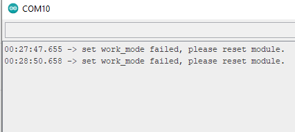
I am having error with this line if(!RAKLoRa.rk_setWorkingMode(0)) //set WisNode work_mode to LoRaWAN.

The only difference is that I’m using P2P examples, receiver and sender codes but to no avail. I updated the baud rates in serial tool to 9600. pins triple checked, updated firmware but I cant seem to make it work.

Capture

I have a pair of RAK811 433mhz v1.3 using arduino uno on both EVBs.

Can you please help.

Thanks!
R

You’ll need to set it to 1 for P2P and as above:

I think you’ll find it’s done it - but the library expects a response which it doesn’t get due to above. Just set it the once at the same time as setting the baud rate.

From a direct message, copied here so that all can benefit.

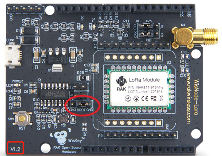
@rlpdavid, if you have a v1.2 board, you will need to remove at the very least, R12 & 13 as these are connected to the Arduino’s serial port, the one you use to program it with, so this will solve the lack of communication.

R8 appears to reset the shield if the Arduino is reset and R11 allows you to reset the shield via D8 from your code (a good thing to have).

There is level shifting on the shield to handle the different voltages, so you are all good in that dept.

NMCC and Nicholas. Thank you for your replies. I have been through all the references and have learnt heaps. However, I’m still a bit stuck. Leaving aside mounting the Wisnode on a Mega, I have managed to get the standalone Wisnode to join my gateaway/TTN The join request was acknowledged/established the moment I put a payload into the node;

at+send=lora:1:12345678

So my next question is how do I put a “real” payload into the node?

I have this piece of code from the RAKWireless/WisNode-Arduino-Library

/********************************************************

  • This demo is only supported after RUI firmware version 3.0.0.13.X on RAK811
  • Master Board Uart Receive buffer size at least 128 bytes.
    ********************************************************/

#include “RAK811.h”
#include “SoftwareSerial.h”
#define WORK_MODE LoRaWAN // LoRaWAN or LoRaP2P
#define JOIN_MODE OTAA // OTAA or ABP
#if JOIN_MODE == OTAA
String DevEui = “8680000000000001”;
String AppEui = “70B3D57ED00285A7”;
String AppKey = “DDDFB1023885FBFF74D3A55202EDF2B1”;
#else JOIN_MODE == ABP
String NwkSKey = “69AF20AEA26C01B243945A28C9172B42”;
String AppSKey = “841986913ACD00BBC2BE2479D70F3228”;
String DevAddr = “260125D7”;
#endif
#define TXpin 11 // Set the virtual serial port pins
#define RXpin 10
#define DebugSerial Serial
SoftwareSerial ATSerial(RXpin,TXpin); // Declare a virtual serial port
char buffer[]= “72616B776972656C657373”;

bool InitLoRaWAN(void);
RAK811 RAKLoRa(ATSerial,DebugSerial);

void setup() {
DebugSerial.begin(115200);
while(DebugSerial.available())
{
DebugSerial.read();
}

ATSerial.begin(9600); //set ATSerial baudrate:This baud rate has to be consistent with the baud rate of the WisNode device.
while(ATSerial.available())
{
ATSerial.read();
}

if(!RAKLoRa.rk_setWorkingMode(0)) //set WisNode work_mode to LoRaWAN.
{
DebugSerial.println(F(“set work_mode failed, please reset module.”));
while(1);
}

RAKLoRa.rk_getVersion(); //get RAK811 firmware version
DebugSerial.println(RAKLoRa.rk_recvData()); //print version number

DebugSerial.println(F(“Start init RAK811 parameters…”));

if (!InitLoRaWAN()) //init LoRaWAN
{
DebugSerial.println(F(“Init error,please reset module.”));
while(1);
}

DebugSerial.println(F(“Start to join LoRaWAN…”));
while(!RAKLoRa.rk_joinLoRaNetwork(60)) //Joining LoRaNetwork timeout 60s
{
DebugSerial.println();
DebugSerial.println(F(“Rejoin again after 5s…”));
delay(5000);
}
DebugSerial.println(F(“Join LoRaWAN success”));

if(!RAKLoRa.rk_isConfirm(0)) //set LoRa data send package type:0->unconfirm, 1->confirm
{
DebugSerial.println(F(“LoRa data send package set error,please reset module.”));
while(1);
}
}

bool InitLoRaWAN(void)
{
if(RAKLoRa.rk_setJoinMode(JOIN_MODE)) //set join_mode:OTAA
{
if(RAKLoRa.rk_setRegion(5)) //set region EU868
{
if (RAKLoRa.rk_initOTAA(DevEui, AppEui, AppKey))
{
DebugSerial.println(F(“RAK811 init OK!”));
return true;
}
}
}
return false;
}

void loop() {
DebugSerial.println(F(“Start send data…”));
if (RAKLoRa.rk_sendData(1, buffer))
{
for (unsigned long start = millis(); millis() - start < 90000L;)
{
String ret = RAKLoRa.rk_recvData();
if(ret != NULL)
{
DebugSerial.println(ret);
}
if((ret.indexOf(“OK”)>0)||(ret.indexOf(“ERROR”)>0))
{
DebugSerial.println(F(“Go to Sleep.”));
RAKLoRa.rk_sleep(1); //Set RAK811 enter sleep mode
delay(10000); //delay 10s
RAKLoRa.rk_sleep(0); //Wakeup RAK811 from sleep mode
break;
}
}
}
}


The payload sits here -

char buffer[]= “72616B776972656C657373”;

(1) How do I, for instance, get sensor data into here?

(2) And while I’m at it, how do I get that code above into my Wisnode?

I’ll bet that’s pretty simple for someone, but right now, not for me.

Many thanks. Regards.

The WisNode is a self-contained module, as you’ve discovered.

The code above goes on to the Arduino Mega and you send the commands to the WisNode from your code to get it to send your payload. So you will need to:

If not already, get the Arduino IDE installed

  • Read about Arduino programming 101
  • Put the starter code above on your Mega and test
  • Write the code to read your sensors - what are they?
  • Write the code to put the data from the sensors in to the buffer.

If you get started with the first three bullet points and tell us what sensors you have, we’ll be here when it’s time to code them.

Hi Nick. I have a DHT22 module connected to a Dragino LoRa shield mounted on a Arduino Mega. I wrote the code. Its set up as a node. I get the temp and the humidity off the TTN. Works perfectly. It works exactly as you describe above. I have a total of 4 nodes installed and working.

I have a really major project going here that I designed and wrote the code for that manages water delivery across the farm. It prioritises the use of water across humans, animals, and vegetation. It get the time of GPS to determine summer time/winter time, and accordingly restricts irrigation. It detects the presence if rain and inhibits irrigation.

I have done Arduino 101 and I can write in C (among other programming languages). I have Arduino IDE installed.

Cld you please confirm one thing. The Wisnode does not get mounted on the Mega. It sits on its own with jumper connection to Rx/Tx pins … plus VCC?

If do mount it on the Mega, I have to break the 4 resistors 12, 13, 17, 19.

Thank you for your help. Regards

I think part of my problem is use of the word “stand alone”. If Wisnode was stand alone, I’d have thought the sensor was connected directly to the Wisnode, and the code installed on the Wisnode.

I think if I regard it as a shield, then I don’t have a problem … except for the 4 resistors that have to be removed.

The WisNode does not need anything else for you to connect to LoRaWAN - that’s my meaning of standalone. But it’s tricky to connect sensors & program for but the facility is there if you want to get in to RUI.

So if you follow the instructions for which ever version of WisNode you have - I think v3 is jumpers and the others are resistors that need removing - you can then treat it as a shield, plug it on top of your Mega and use the library linked to above which allows you to code the same commands that you typed in directly.

Or yeah, link over to Rx & Tx plus GROUND and leave it next to your Mega but not plugged in. I use SoftSerial at 9600 so I’ve still got the main USB serial port for debug and programming.

Great. Thanks. To labour the point, if I purchase a v1.3, I don’t have to remove the resistors, and I can mount the Wisnode on the mega and then follow the tram lines?

I know the answer, but this is definitely in the flogging a dead horse territory and we are in a ‘teach a man to fish’ mood.

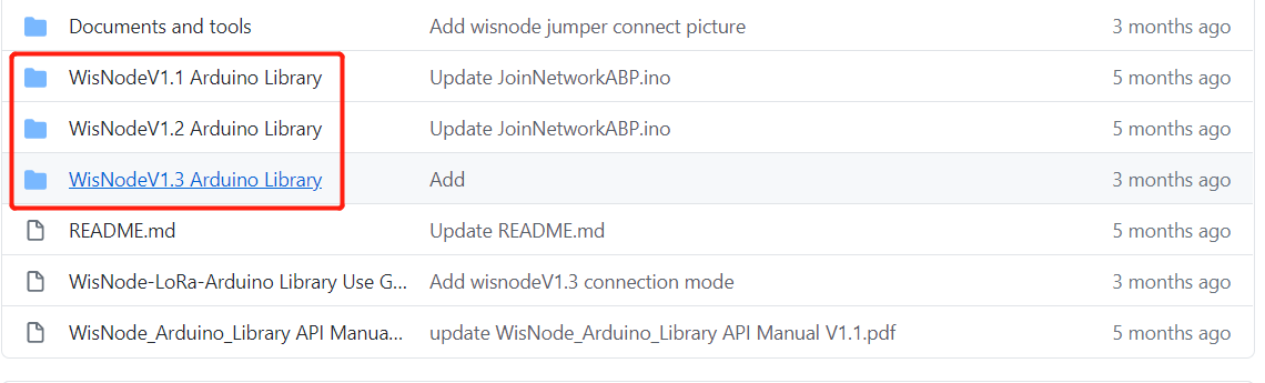
So, what does the document specifically for the v1.3 say - or more importantly, what does it show on the picture?

PS, yes, it’s a bit of an egg hunt as not all the docs are in the same place, but places do absolutely scream V1.3 …

Hi Nick. I’m not sure what your first para means. Most of my professional career was in Software Engineering. I was part of a team ion the UK who developed the world’s first electronic telephone exchange for the British Post Office. Pretty sure I know how to fish. I am keen to learn how to use AT commands, and also to use RUI. I think my biggest challenge is the lack of absolutely clear documentation.

I tried to update the firmware on my Wisnode/RAK811 board. It took a whole day. Had to reload the boot-loader as well. Now AT commands dont work. However, I will persevere and I will get it going.

Hate to say, I have looked at every v1.3 doc I can find, but as yet haven’t found a picture that you refer to.

Rome wasn’t built in a day, but it was built.

Thank you for your assistance to date. Undoubtedly, you have helped me make progress.

Just BTW, if I ordered a new Wisnode … which now appears to be called Wisduo, will I automatically get a v1.3?

Regards.

Dear John,
The V1.3 mentioned by nick is the corresponding hardware model of wisnode. For different reasons, the latest hardware has been upgraded to V1.3, and the arduino connection method corresponding to it has also changed. You must refer to the documentation of the corresponding model. Connect to ensure the normal operation of the program.

Thank you for your reply. Much appreciated.

I think I now have a good understanding of the issues surround interfacing a Mega to a Wisnode RAK811. So before I ventured any further, I thought I’d upgrade the firmware on the Wisnode, I followed the TTN instruction to the letter.

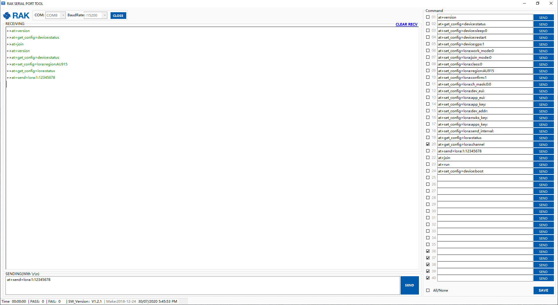
That took some doing. I ended up reloading the boot loader as well as the firmware (to V3.0.0.14T3). However, when I go to RAK Serial Port Tool, i can out in any at command but I don’t get any response as per the screen shot below.

I have 4x Wisnodes v1.2. The first one tried this on has had R11, R12 etc decimated for mounting on the Mega. I got the response as per the screen shot.

So I tried another virgin Wisnode. I got the same screen shot. No response to the AT commands.

I reverted to the third virgin Wisnode just to be sure and it works like a charm as a standalone node.

Can anyone help me with this please

Regards.

Dear,
Can you show your Wisnode connection diagram? I want to find some problems through it. Before this, you must ensure that the firmware is programmed normally.

Very happy to do that. I’ll get onto it. Thanks.

Dear,

Have a question. You must burn firmware on github If you want to using RAK wisnode and Arduino.

Hi again. I think I have mixed up two issues here, so let me separate them and talk about them.

  1. On my v1.2 Wisnode I installed bootloader “RAK811_BOOT_V3.0.2”, and I upgraded the firmware to “RAK811_HF_V3.0.0.13.T3”.

Following that, I used the RAK Serial Port to implement some AT codes on the Wisnode.

There was no response to the AT command on the PC screen.

I reduced the baud rate from 115200 to 9600 and the responses appeared!!

I have that Wisnode working as a standalone node to my gateway and can see it on the TTN console.

I have no idea why it would not work on 115200 when it was working successfully prior to upgrading the firmware.

  1. I am trying to drive a Wisnode v1.2 from an Arduino Mega.

I am about to run jumpers from the Arduino to the Wisnode and send a payload every 10 seconds to test out that hardware interconnection.

I am using the example from Github.

I will report on how that goes, shortly.

Regards.

Dear,

1.I reduced the baud rate from 115200 to 9600 and the responses appeared!!

Sorry, no problem was found, this is set in the firmware, you can modify the baud rate by AT command, 9600 is to adapt to the command sent by the arduino development board.

I am trying to drive a Wisnode v1.2 from an Arduino Mega.

Looking forward you report.

It means that I’m trying to encourage action between messages - I’d linked to the Arduino library with the documentation for v3 that has the picture and mentioned the jumpers and mentioned baud rates and I am only human …