I’m trying to set up a 5860 cellular modem with the 11310 core. I’m using the code example Hologram_Ping_LTE.ino from the IDE. When I upload the compiled sketch, nothing appears to happen and I’m not getting any indication from Hologram that the SIM has even appeared on the network.
Adding to this is the fact that I have no visibility into the device. When I connect the USB cable to a host and scan the bus, I see it appear briefly every few seconds, disappear, and then reappear with a device ID incremented by one. Output of lsusb at 800 ms intervals:
Bus 001 Device 001: ID 0000:0000
Bus 001 Device 001: ID 0000:0000
Bus 001 Device 001: ID 0000:0000
Bus 001 Device 114: ID 2c7c:0700
Bus 001 Device 001: ID 0000:0000
Bus 001 Device 001: ID 0000:0000
Bus 001 Device 001: ID 0000:0000
Bus 001 Device 001: ID 0000:0000
Bus 001 Device 115: ID 2c7c:0700
Bus 001 Device 001: ID 0000:0000
Bus 001 Device 001: ID 0000:0000
Bus 001 Device 001: ID 0000:0000
Bus 001 Device 001: ID 0000:0000
Bus 001 Device 116: ID 2c7c:0700
Bus 001 Device 001: ID 0000:0000
Bus 001 Device 001: ID 0000:0000
Bus 001 Device 001: ID 0000:0000
Bus 001 Device 001: ID 0000:0000
Bus 001 Device 117: ID 2c7c:0700
Bus 001 Device 001: ID 0000:0000
May I know where your are testing the RAK5860? Not all countries are supported by Hologram for LTE CAT-M1. RAK5860 only works for NB-IoT or LTE-M and not on the standard LTE we usually use.
I re-read your first post. It seems the issue is still on the WisBlock Core level. Can you upload a basic LED blink? If not since your board is not detected. Maybe you can try to reupload the firmware using the guide here - RAK11300 Module Quick Start Guide | RAKwireless Documentation Center. If it is still not working, if you possible, you can try a different USB cable or in a different PC/port. Btw, what WisBlock Baseboard are you using?
This is with the core and modem that respond normally. I still haven’t got the other one working. Other example sketches work, including blink.ino.
I’ve tried different USB cables and ports on the PC. It’s a dual IO baseboard 19011. The connectivity I’m trying to establish is via the USB connector on the 5860.
a) No consistent USB device detection. As you can see from the output of lsusb above, the computer “discovers” it about once every 4s. Then it disappears and the next time it shows up with an increment to the device ID…
b) I have no idea whether the serial connection is being established, as I have no feedback.
I have a good 18650 battery connected, the blue LED cycles on for 4 s and off for 1, and the green LED cycles on for 0.5 s and off for about 4.
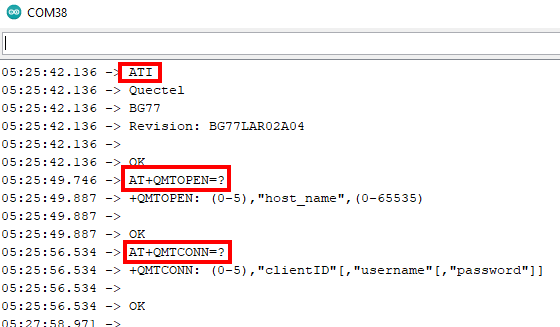
Hi @carlrowan. I’m now seeing serial monitor output but it appears to have the same problem with stability. When I load BG77_Unvarnished_Transmission and issue several AT commands, I only see one of them and no OK in response. Notice the 4 second interval between RDY messages…I think there is a correlation here with the LED cycle and it also seems to fit with the USB device detection observed:
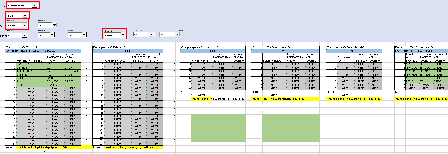
Update: I got one to work with a different 11310 core. After some more experimentation I found that the 15001 flash module was causing the problem. Removing this from the base allowed the 5860 to initialise and accept AT commands. Now I have done successful network pings and sent TCP packets.
So it appears that I will be unable to use the flash memory module for this project. I will need to optimise lookup tables to keep them small enough to fit in the onboard memory.
I’ll try that again. I did a series of tests with the module in each of the sensor slots and always had one of two failure modes: either a timeout establishing connection with the modem, or the “flapping” behaviour observed RDY appearing every 4 s.
[EDIT] It appears to be working with the 15001 in slot D. I’m running the Hologram_TCP example and have just seen the assembled payload with the GPS coordinates in the serial monitor.